Adjustable Handle for Pneumatic Fastener
- Summary
- Abstract
- Description
- Claims
- Application Information
AI Technical Summary
Benefits of technology
Problems solved by technology
Method used
Image
Examples
second embodiment
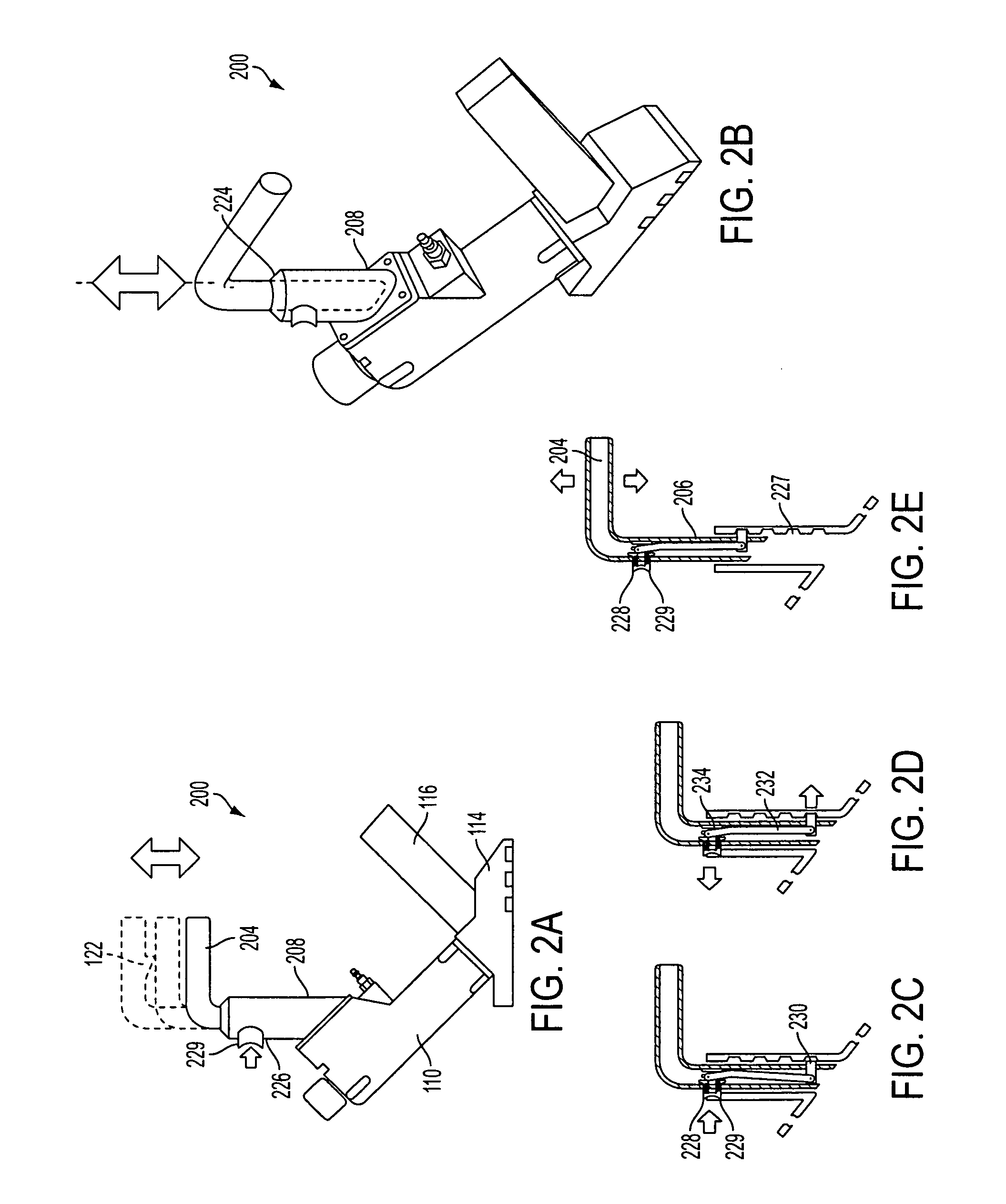
[0027]FIGS. 2A-2E illustrate the present invention. In this exemplary embodiment, the housing 208 of the pneumatic nailer 200 defines a hollow recessed area 224 within which the lower portion 206 of the handle 202 is disposed. The lower portion 206 of the handle 202 is coaxially slidable within the recessed area 224 of the housing 208. A housing aperture 226 is formed through one side of the housing 208 and a plurality of vertically arranged detents or recesses 227 are formed on an opposite side on an internal surface of the housing. A lower handle aperture 228 is formed through a lateral side of the lower portion 206 of the handle 202. The lower handle aperture 228 has, projecting therethrough, a spring-loaded push button 229 that engages and disengages a locking pin 230 as shown in FIGS. 2C-2E. The push button 229 is attached to a spring 234 on an inner surface of the lower portion 206 of the handle 202 laterally opposite to the lower handle aperture 228. The push button 229 is co...
third embodiment
[0028]FIGS. 3A and 3B illustrate the present invention. In this exemplary embodiment, a screw-in fastening knob for adjusting the handle of a pneumatic fastener 300 is illustrated. In this exemplary embodiment, the housing 308 defines a hollow recessed area 324 within which the lower portion 306 of the handle 302 is disposed. The lower portion 306 of the handle 302 is coaxially slidable within the recessed area 324 of the housing 308. A housing aperture 326 is formed through one side of the housing 308. Threaded handle apertures 328 are arranged through the lower portion of the handle 302. In operation, the handle 302 of the pneumatic fastener 300 can be adjusted by aligning the aperture 326 of the housing 308 with at least one of the apertures 328 in the lower portion 306 of the handle. The apertures 328 on the handle 302 are configured to receive a securing member such as a screw-in fastening knob 330. The screw-in fastening knob 330 includes a threaded shaft that can be screwed i...
fourth embodiment
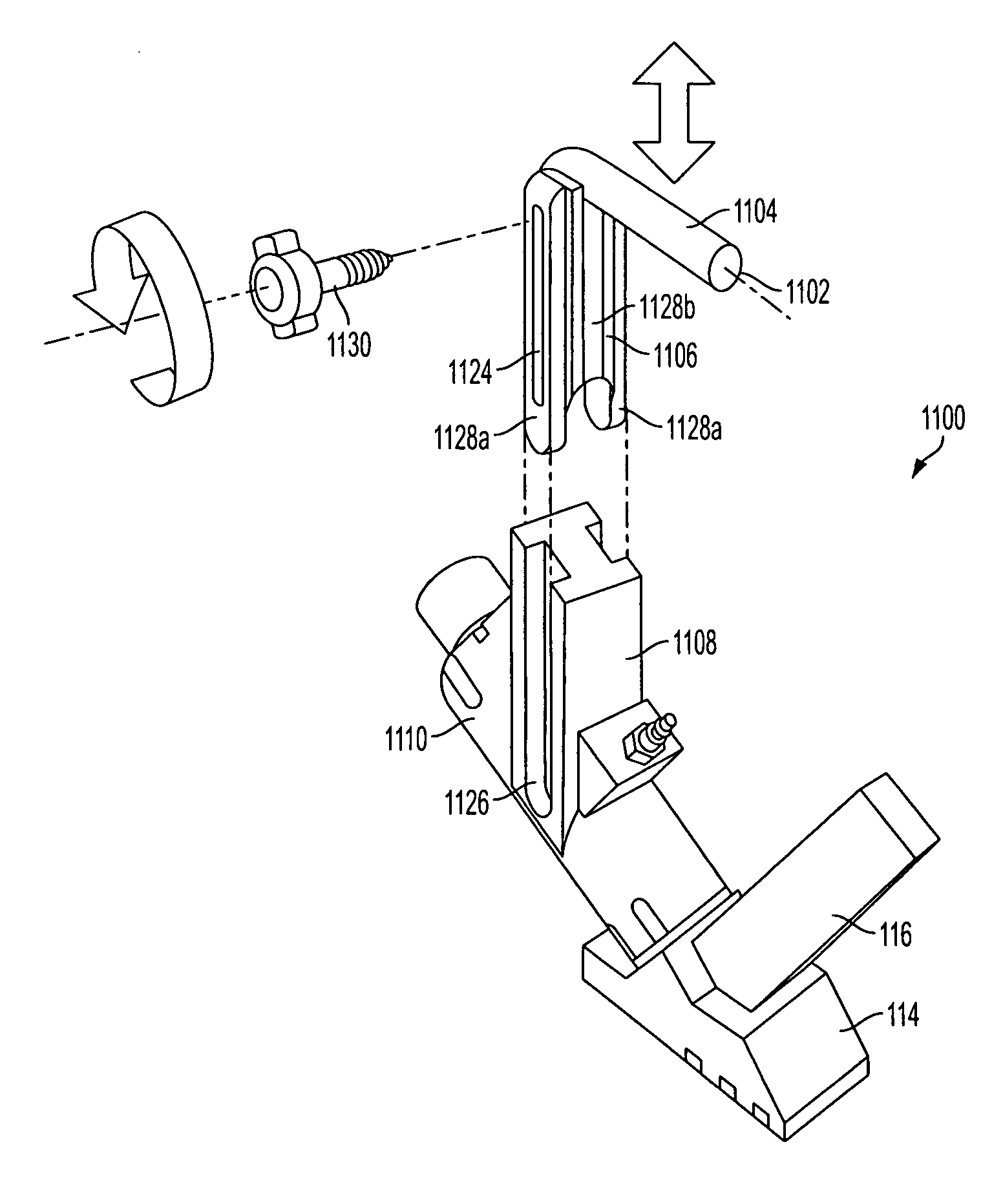
[0029]FIGS. 4A and 4B illustrate the present invention. In this exemplary embodiment, FIGS. 4A and 4B illustrate a sliding handle 402 and clamping lever 430 for adjusting the handle of a pneumatic fastener 400. As shown in the figures, the handle 430 is disposed on an inclined supporting member 408 that is mounted on an upper surface of the main body 110. The supporting member 408 has tracks 405 disposed on opposite lateral sides. The tracks 405 run parallel to the upper surface of the main body 110. The tracks 405 slidingly receive the lower portion 406 of the handle 402, which is formed as a grapple having fingers 414. The grapple fingers 414 are disposed within the track 405 for slidingly moving the handle 402 along the length of the inclined supporting member 408. Once the handle 402 is slid to a desired position or predetermined height on the main body 110, the handle can then be clamped by a clamping lever 430 to secure the handle in position. The clamping lever 430 is rotatab...
PUM
 Abstract
Description
Claims
Application Information
 - R&D
- Intellectual Property
- Life Sciences
- Materials
- Tech Scout
- Unparalleled Data Quality
- Higher Quality Content
- 60% Fewer Hallucinations
Browse by: Latest US Patents, China's latest patents, Technical Efficacy Thesaurus, Application Domain, Technology Topic, Popular Technical Reports.
© 2025 PatSnap. All rights reserved.Legal|Privacy policy|Modern Slavery Act Transparency Statement|Sitemap|About US| Contact US: help@patsnap.com


