LED drive device, LED drive method and lighting system

a technology of led drive and led drive module, which is applied in the direction of instruments, light sources, electroluminescent light sources, etc., can solve the problems of large number of parts, noise, and difficulty in switching on/off, and achieve the effect of efficient switching on/o

Inactive Publication Date: 2010-08-05
FUJI ELECTRIC CO LTD
View PDF5 Cites 119 Cited by
  • Summary
  • Abstract
  • Description
  • Claims
  • Application Information

AI Technical Summary

Benefits of technology

[0008]According to the LED drive device, the first switching element is controlled by the control circuit so that the sum of the value of the current flowing in the first switching element and the value of the current flowing in the second switching element is kept constant.
[0009]According to the disclosed LED drive device, the LEDs can be switched on / off efficiently because the current can be switched smoothly even when there are differences between forward voltages of the LEDs.

Problems solved by technology

The switching method, however, has a problem in that noise occurs at the time of switching, and a problem that a large number of parts are required because the circuit configuration is rather complicated.
Conventional linear control methods also has problems.
Accordingly, there is a problem that efficiency is very poor.
There is however a problem that this method cannot accept differences between forward voltages of LEDs.
There is a problem that the number of processes at the time of shipping increases.

Method used


Image

  • LED drive device, LED drive method and lighting system
  • LED drive device, LED drive method and lighting system
  • LED drive device, LED drive method and lighting system

Examples


Embodiment Construction

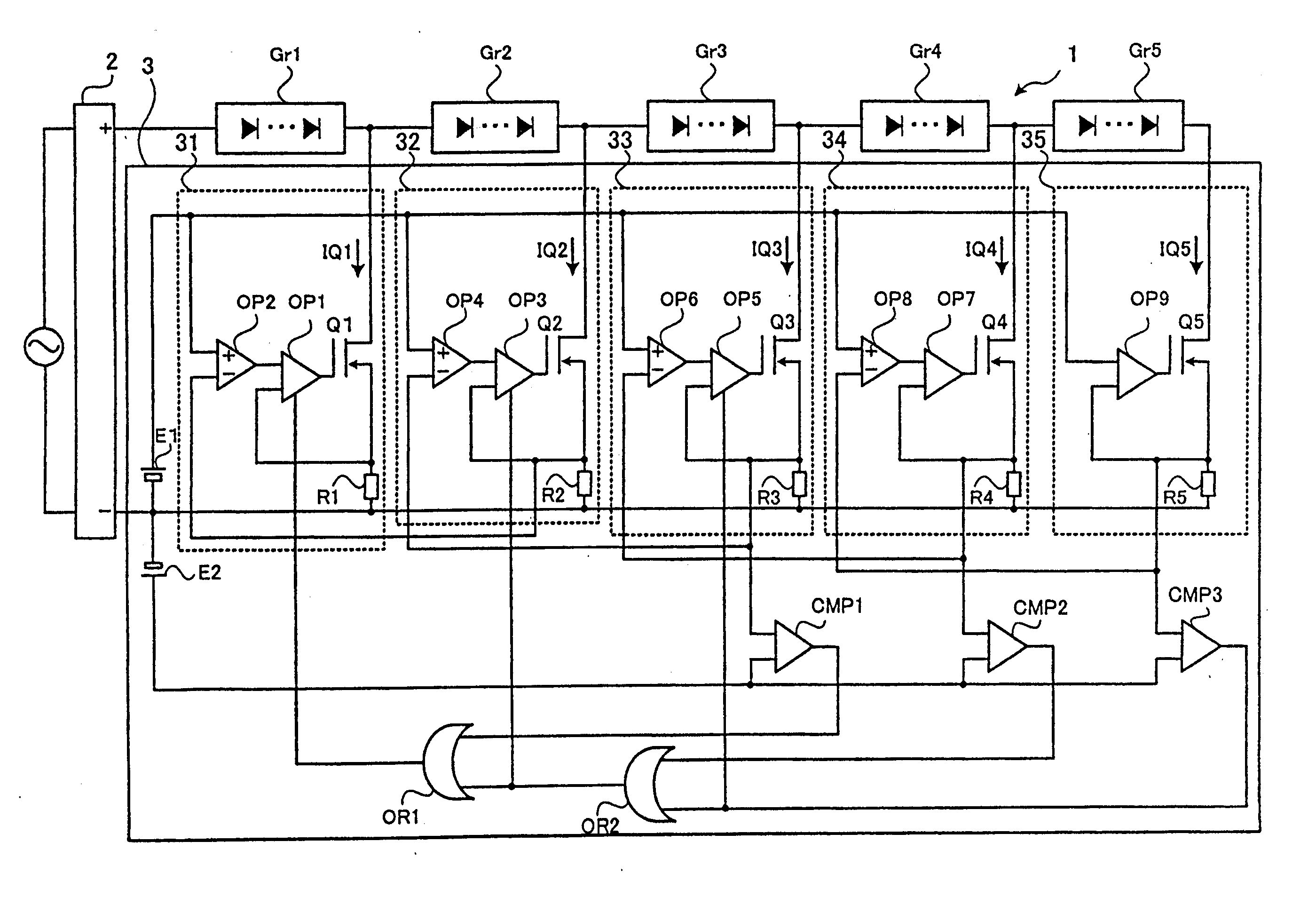
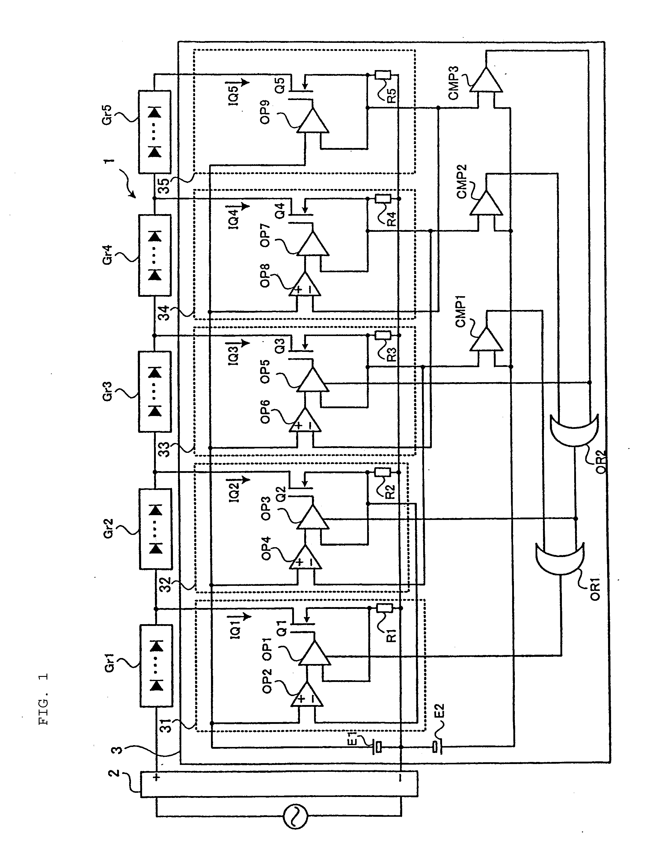
[0017]FIG. 1 is a circuit diagram showing a lighting system according to an embodiment of the invention. The lighting system 1 includes: a full-wave rectifier 2; LED groups Gr1 to Gr5 each of which has a plurality of LEDs; and a drive circuit (LED drive device) 3 which drives the LED groups Gr1 to Gr5. The full-wave rectifier 2 has a diode bridge (not shown) which full-wave rectifies an alternating voltage of 50Hz 100V or 60Hz 100V.

[0018]In the following description, the case where an alternating voltage of 100V is used is taken as an example. It understood, however, that the invention is not limited thereto but can be applied to various alternating voltages. If respective values of resistance, withstand voltage, etc. can be set in accordance with various alternating voltages to be used, the invention can be applied to the various alternating voltages.

[0019]The LED groups Gr1 to Gr5 are driven (switched on) when 20V is applied to the LED groups Gr1 to Gr5. The drive circuit 3 switch...


PUM


Abstract

A drive circuit drives LED groups each of which has a plurality of LEDs connected in series. The drive circuit includes nMOSFETs which drive the LED groups, current regulating circuits which determine drain currents of the nMOSFETs, and subtracters which control the current regulating circuits to keep the sum of the current values of adjacent two nMOSFETs constant. The LEDs can be switched on/off efficiently even when there are differences between forward voltages of the LEDs.

Description

BACKGROUND[0001]The present invention relates to an LED drive device, an LED drive method and a lighting system. Particularly it relates to an LED drive device and an LED drive method for driving a plurality of series-connected LEDs, and a lighting system.[0002]Lighting systems using a plurality of LEDs (Light Emitting Diodes) have recently been developed. A switching method and a linear control method have been used as control methods in the lighting systems. The former method uses a switching power supply circuit for supplying a constant current from an AC power supply to each LED. The latter method detect an AC voltage or a current flowing in LEDs and changes the number of switched-on LEDs to minimize power supply loss. Examples of conventional systems are illustrated in JP-A-2006-244848, JP-A-2008-59811 and JP-A-2006-147933[0003]The switching method, however, has a problem in that noise occurs at the time of switching, and a problem that a large number of parts are required beca...

Claims


Application Information

Patent Timeline
Patent Type & Authority Applications(United States)
IPC IPC(8): H05B37/02
CPCH05B33/083H05B45/48
Inventor KUWABARA, KESANOBU
Owner FUJI ELECTRIC CO LTD
Why Eureka
Try Eureka