Illuminated waterfall apparatus

a technology of illumination apparatus and waterfall, which is applied in the field of illumination waterfall apparatus, can solve the problems of complex sealing arrangement, difficult handling, inserting and sealing of individual optical fibres, and the lighting effect produced by this arrangement is less than ideal

Inactive Publication Date: 2010-08-05
ASTRAL POOL AUSTRALIA
View PDF13 Cites 18 Cited by
  • Summary
  • Abstract
  • Description
  • Claims
  • Application Information

AI Technical Summary

Benefits of technology

This patent describes how multiple small lights can be placed together to create an even distribution of color on a surface. These lights are organized into groups, with each group having its own unique pattern. By combining the patterns from all the groups, a consistent appearance is achieved across the entire surface.

Problems solved by technology

The technical problem addressed in this patent is how to improve the design of illuminated waterfalls to achieve better lighting effects without compromising their natural appearance or requiring expensive and difficult sealing arrangements. Existing solutions include adding fiber optic cables or employing light probes, but these methods often resulted in uneven lighting or poor performance. There is thus a desire for an innovation that overcomes these issues and offers an effective yet cost-efficient solution for illuminated waterfalls.

Method used


Image

  • Illuminated waterfall apparatus
  • Illuminated waterfall apparatus
  • Illuminated waterfall apparatus

Examples


Embodiment Construction

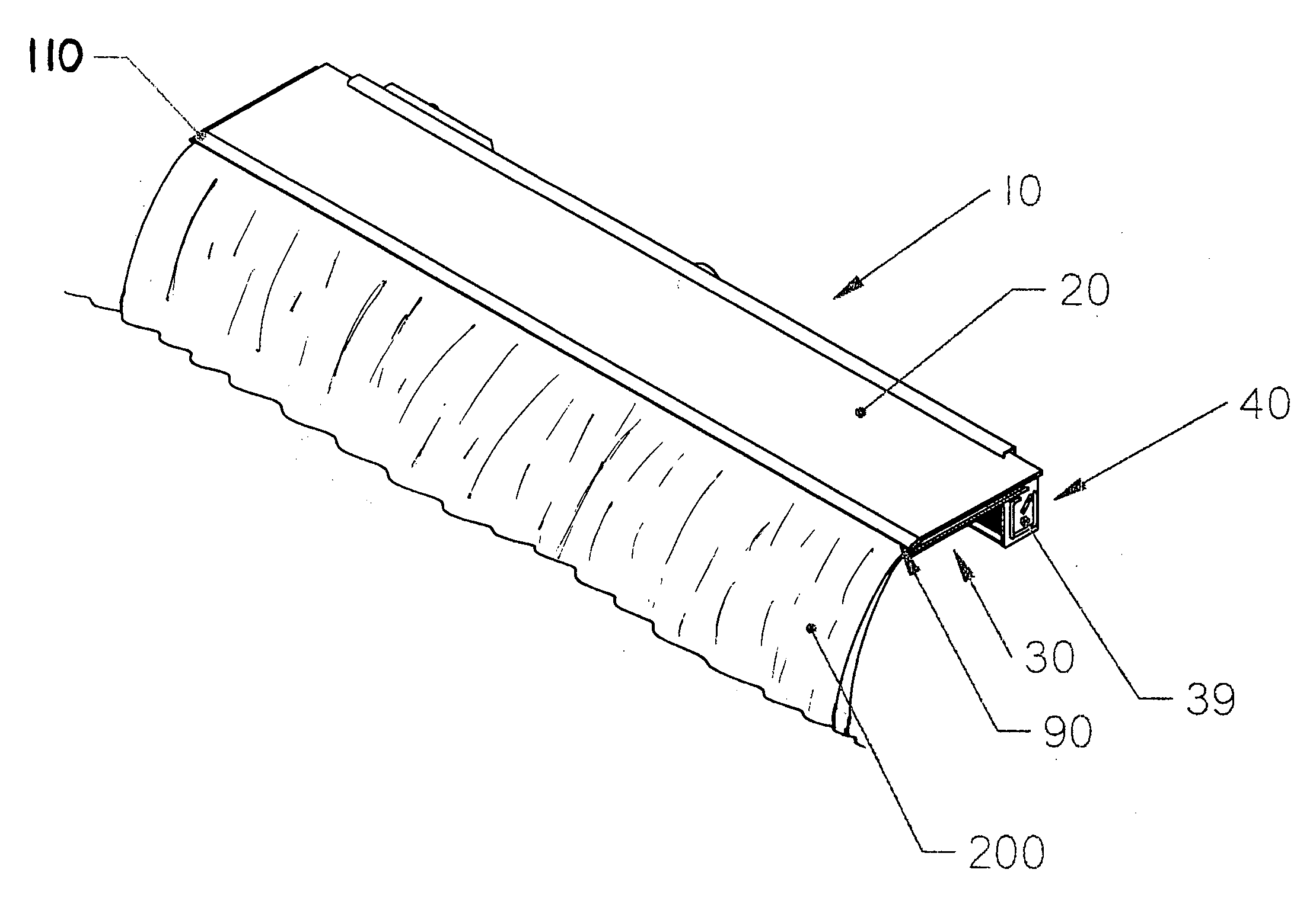
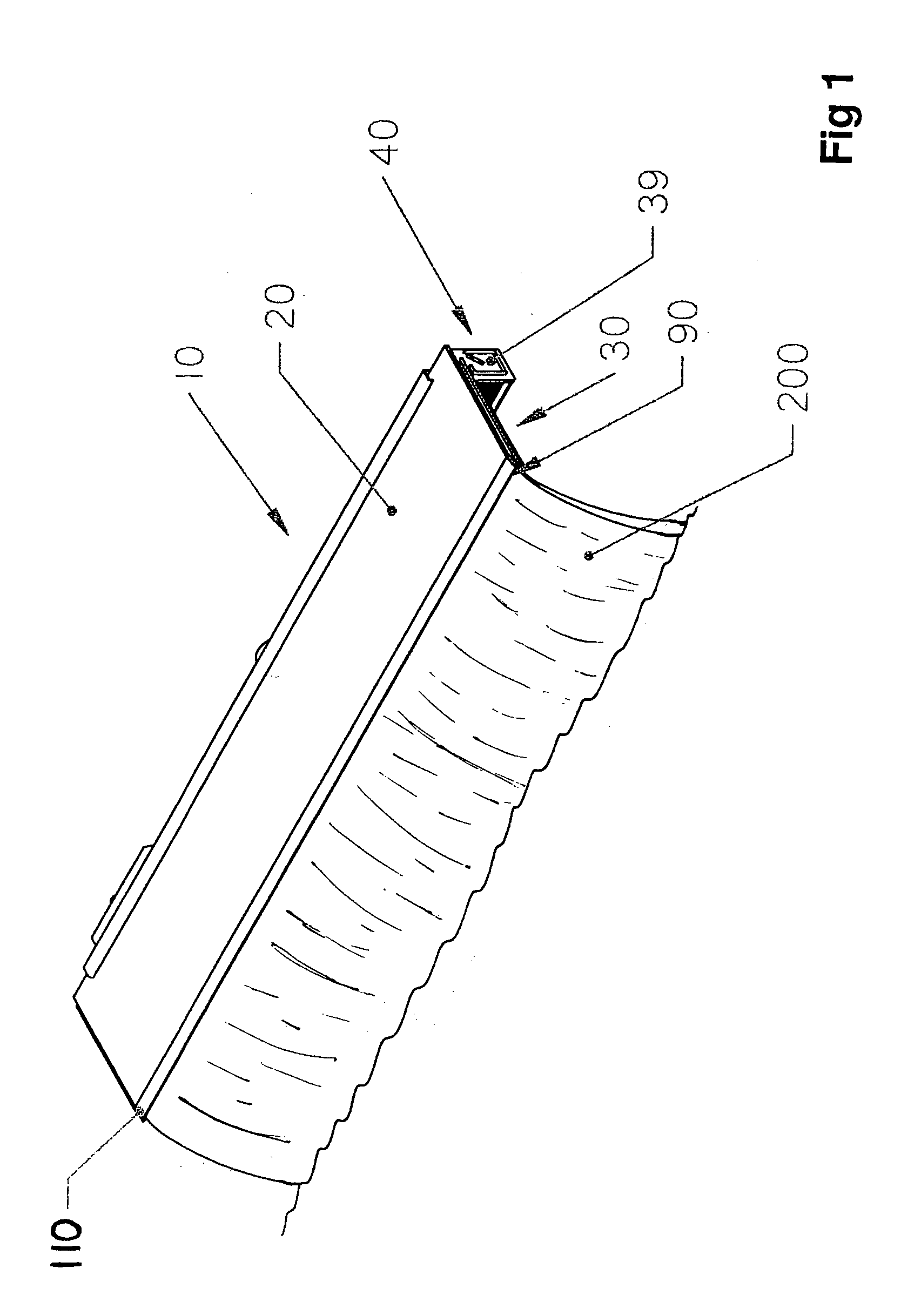
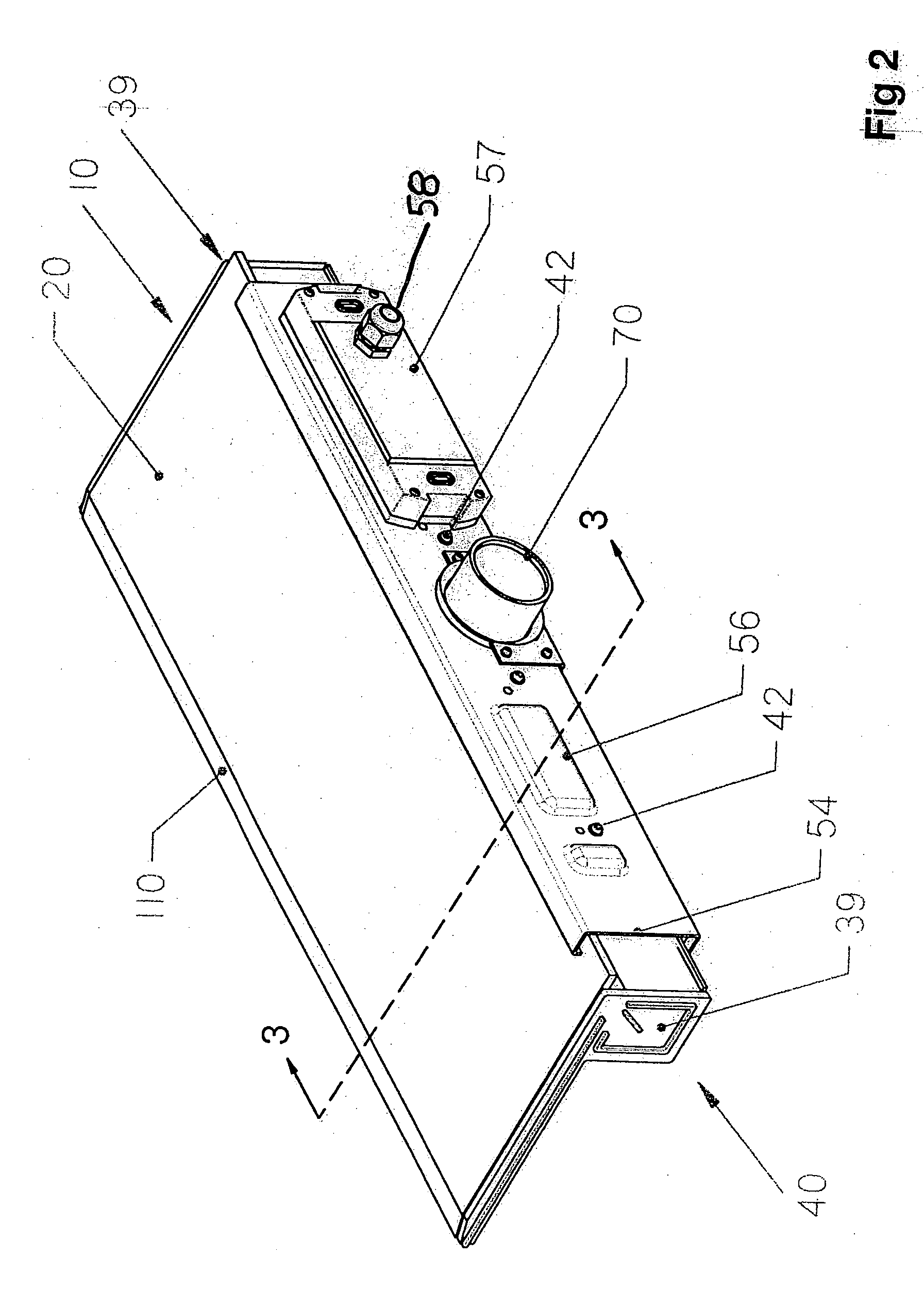
[0026]The illuminated waterfall apparatus 10 has four principal components: an upper plate 20 of a light transmissible material (e.g. Perspex), a lower plate 30, a water manifold 40 and a light source in the form of spaced LEDs 50.

[0027]As shown, the water manifold 40 is an elongate channel structure defining an elongate chamber 40C. Plates 20, 30 extend horizontally from the open top of manifold 40 and are spaced to define a flow path in the form of a relatively long but thin cavity 60. Plate 20 has a lower surface 120 (FIG. 4) that partly defines an outer periphery of the cavity 60. Cavity 60 extends from the manifold 40 to an outlet opening in the form of horizontal slot-like frontal outlet opening 90 at the free, outer ends of plates 20, 30. In operation a stream 200 of water falls freely from the frontal outlet opening 90.

[0028]Plates 20,30 are respectively sealingly connected at their rear margins to rear and front manifold walls 40A and 40B at longitudinal seal structures 130...


PUM


Abstract

An illuminated waterfall apparatus (10) having structure (20, 30) defining an inlet (220) for receiving water, an elongate outlet opening (90) that in situ extends substantially horizontally, a flow path (60) for conveying water from the inlet (220) to the outlet opening (90) from which in operation the water falls in a freely falling stream (200), and a light transmission solid (20) for transmitting light. The light transmission solid (20) is arranged to at least partly define an outer periphery of the flow path (60). The apparatus (10) further includes one or more light sources (50) arranged to project light into the light transmission solid (20) and an optical feature (110) associated with the light transmission solid (20) and being at least approximately parallel to the outlet opening (90) for along the length of the outlet opening (90) deflecting light transmitted by the light transmission solid (20) into the water so that the light is transmitted by the stream of water (200) falling from the outlet opening (90) to produce a decorative effect viewable from in front of the outlet opening (90).

Description


Claims


Application Information

Patent Timeline
Owner ASTRAL POOL AUSTRALIA
Why Eureka
Try Eureka