Uniform light emitting lamp structure

a technology of light-emitting lamps and lampshades, which is applied in the direction of semiconductor devices for light sources, non-electric lighting, lighting and heating apparatus, etc., can solve the problems of non-uniform light emission and significant drop in brightness of lateral lights, and achieve uniform light-emitting effects

Active Publication Date: 2012-07-05
EPISTAR CORP
View PDF5 Cites 18 Cited by
  • Summary
  • Abstract
  • Description
  • Claims
  • Application Information

AI Technical Summary

Benefits of technology

[0008]Therefore, it is a primary objective of the invention to provide a uniform light emitting lamp structure making use of different refractive indexes of a light guide column and an environmental medium to change a light emitting path, such that a portion of the light is emitted with an angle to a rear side of a lamp holder, and the lamp structure has a uniform light emitting effect.

Problems solved by technology

Therefore, a general LED bulb 10 usually has the problem of a non-uniform light emission caused by an insufficient illumination angle of the LED light source 13; particularly, the brightness of lateral lights will drop significantly or even the problem of producing a showdown arises, since the light is blocked by the lamp holder 11.

Method used


Image

  • Uniform light emitting lamp structure
  • Uniform light emitting lamp structure
  • Uniform light emitting lamp structure

Examples


Embodiment Construction

[0025]The assembly and overall operation method of the present invention to achieve the foregoing objectives and effects will become apparent with the detailed description of preferred embodiments together with related drawings as follows:

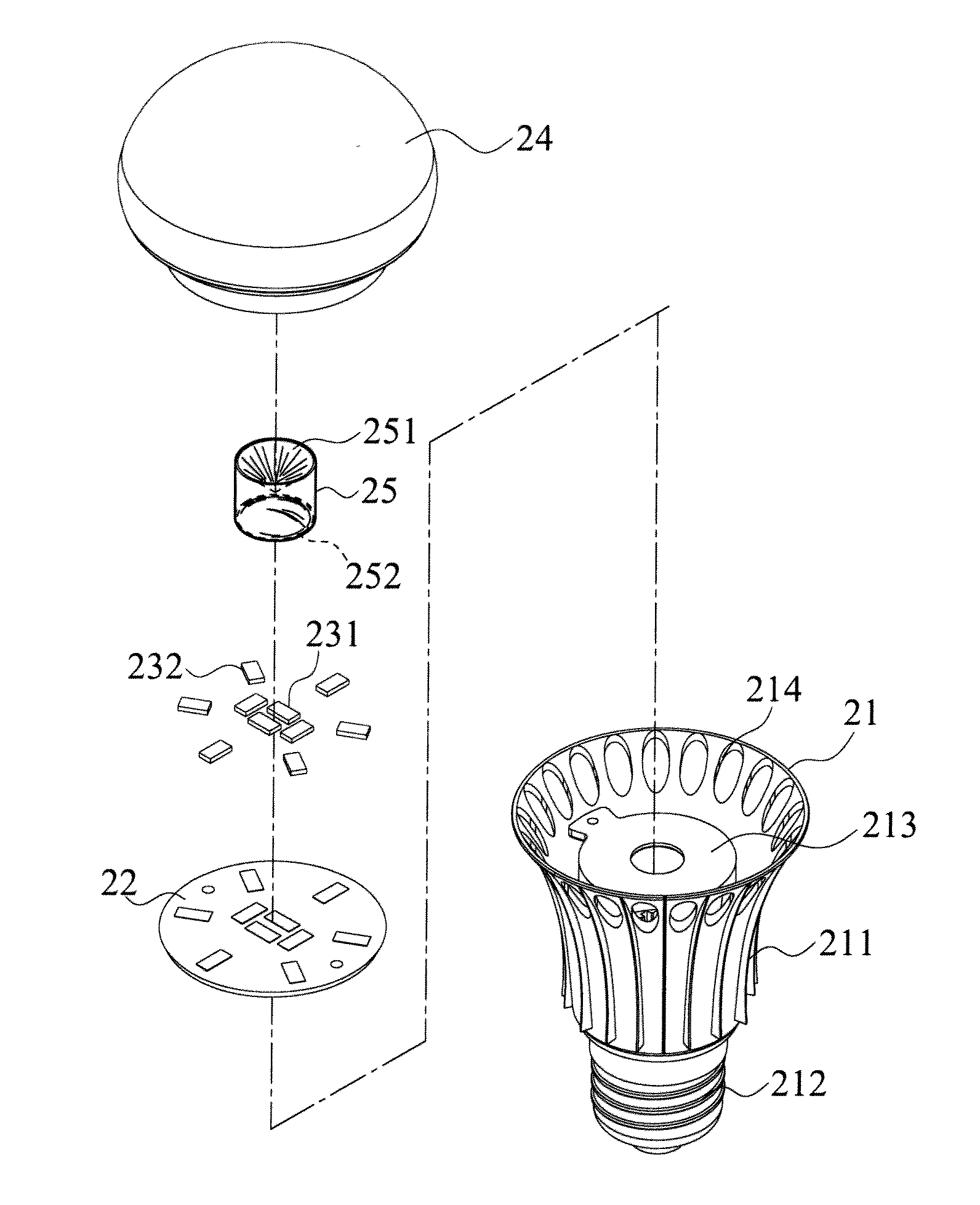
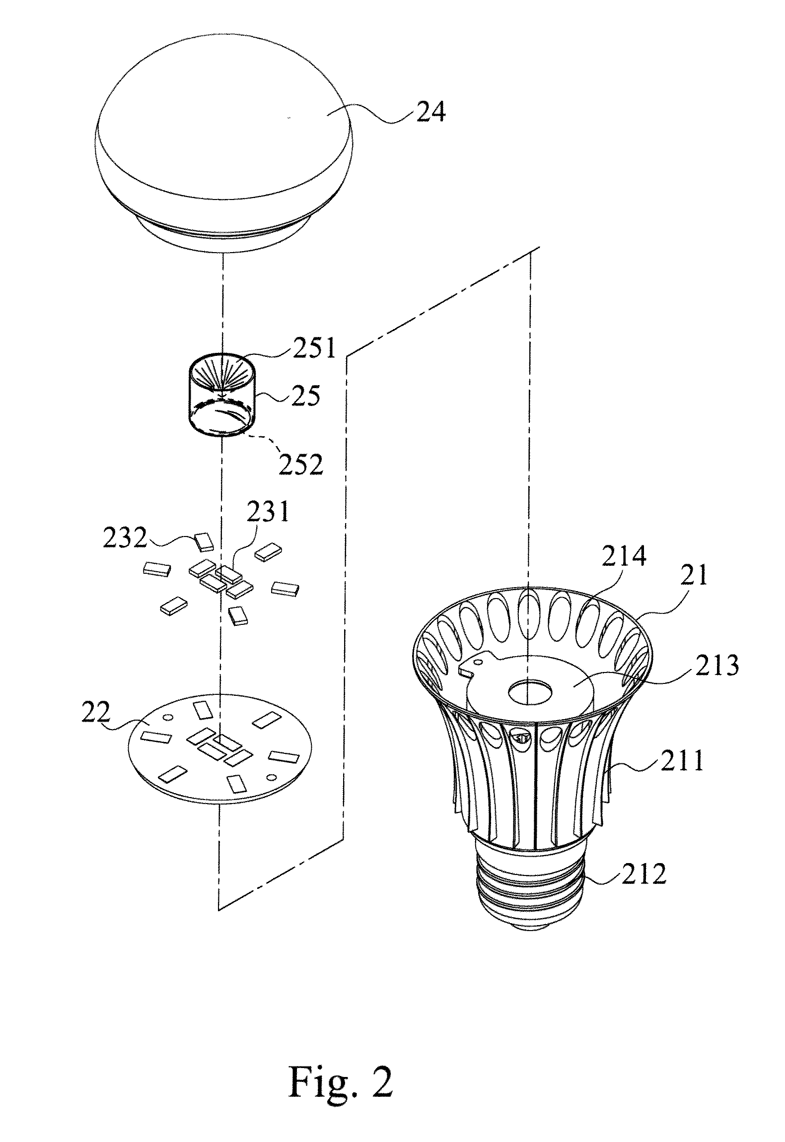
[0026]With reference to FIGS. 2 and 3 for an exploded view and a cross-sectional view of a lamp structure in accordance with a preferred embodiment of the present invention respectively, the lamp structure 20 comprises a lamp holder 21, a circuit board 22, an LED light source 23, a lamp cover 24 and a light guide column 25.

[0027]The lamp holder 21 is a circular cylindrical structure made of aluminum, whose surface includes a plurality of ribs 211 provided for dissipating heat, and an electric connection portion 212 and a planar portion 213 are disposed on both end surfaces of the lamp holder 21 respectively. In addition, the electric connection portion 212 is in the shape of a screw thread, a guide column or an insert pin. Further, the lamp holder ...


PUM


Abstract

The present invention discloses a uniform light emitting lamp structure including a lamp holder, an electric connection portion and a planar portion disposed on both end surfaces of the lamp holder respectively, and the planar portion includes a circuit board electrically coupled to the electric connection portion. The lamp structure further includes an LED light source, a lamp cover and a light guide column with a refractive index n1. After the light of the LED light source is projected from an environmental medium with a refractive index n2 to the light guide column, a portion of the light is reflected from the critical plane in a direction corresponding to the lamp holder through reflections and refractions, such that the light of the LED light source is projected in the environmental medium to achieve the uniform light emitting effect.

Description

BACKGROUND OF THE INVENTION[0001]1. Field of the Invention[0002]The present invention relates to the field of illumination devices, and more particularly to an uniform light emitting lamp structure that increases an angle of illumination by using a light guide column to achieve a uniform light emitting effect.[0003]2. Description of the Related Art[0004]In a light emitting diode (LED), a positive voltage is applied to an LED chip to emit monochromic discrete light, and the light of a desired wavelength can be emitted by the LED if the chemical composition of the LED chip is changed appropriately. In particular, after white LED was introduced, the LED is used extensively in illumination devices. With the advantages incomparable by traditional light sources, the LED is driven by a lower voltage (5V˜24V) to emit light, and thus it can achieve a power saving effect. Under an appropriate application environment or with a good heat dissipation system, the LED has a much longer using life ...

Claims


Application Information

Patent Timeline
Patent Type & Authority Applications(United States)
IPC IPC(8): H01K1/30
CPCF21K9/135F21K9/1355F21V2200/00F21V7/0091F21V7/09F21V7/0066F21K9/23F21K9/232F21K9/60
Inventor WU, CHIH-HSIENTSAI, SEN-YUH
Owner EPISTAR CORP
Why Eureka
Try Eureka