
Loudspeaker position estimation

Active Publication Date: 2010-08-05
BANG & OLUFSEN
View PDF13 Cites 23 Cited by
  • Summary
  • Abstract
  • Description
  • Claims
  • Application Information

AI Technical Summary

Benefits of technology

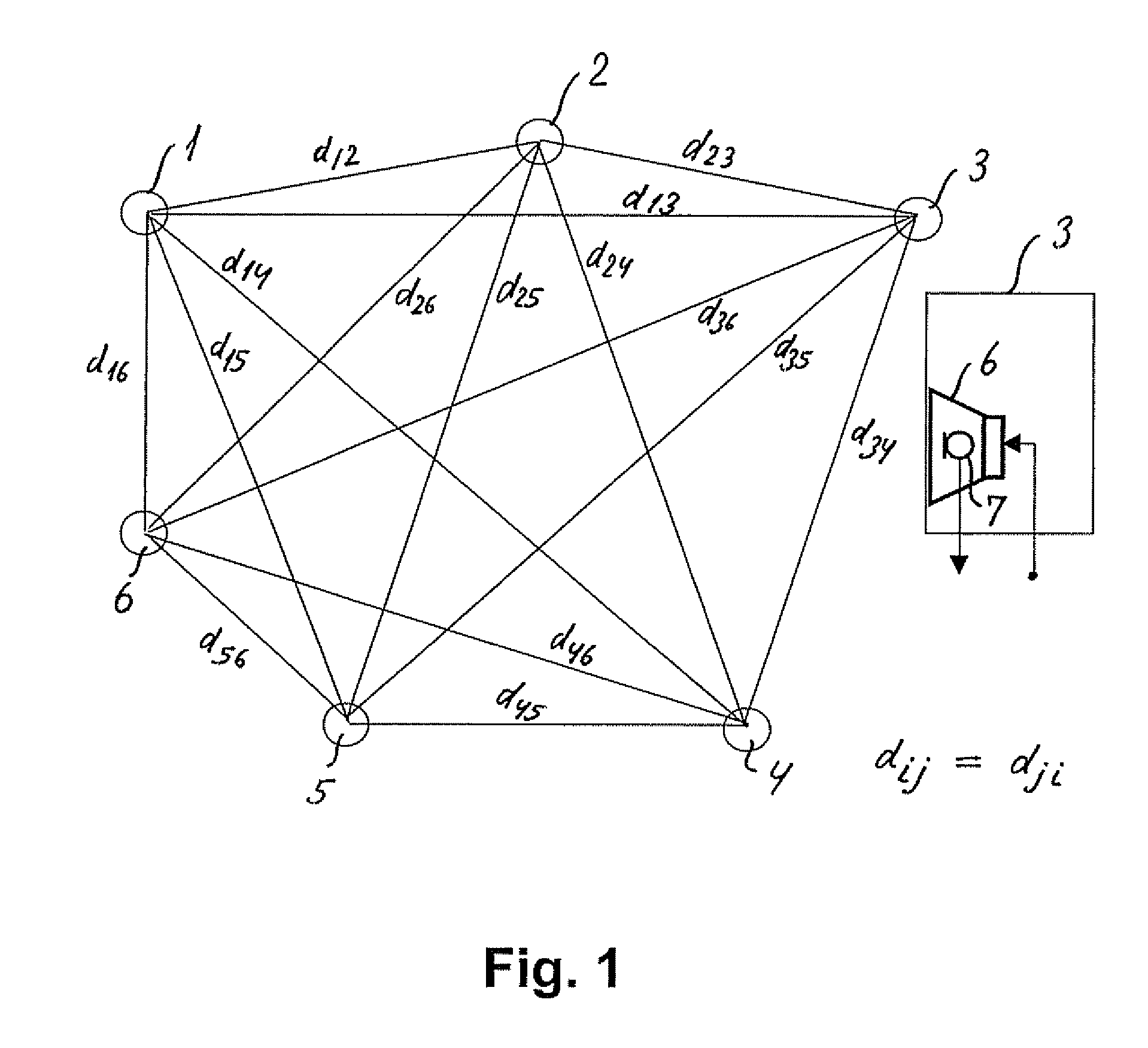
[0016]A special case arises where the shape of the listening room and the actual positions of given loudspeakers within the room are such that sound emitted from one or more given loudspeakers in a loudspeaker set-up can not propagate directly to one or more other loudspeakers of the set-up due to wall portions preventing direct sound propagation. This situation could for instance occur in a listening room of an L-shape. This situation results in at least one of the distances between a given pair of loudspeakers determined based for instance on the corresponding measured impulse response being erroneous, thereby leading to an erroneous estimation of the individual co-ordinates of the loudspeakers when the erroneous distance matrix is used by the MDS algorithm to estimate the co-ordinates. An L-shaped room is only one specific case, where such problems could occur, and also other room shapes or obstacles in the room, such as large furniture pieces, could lead to similar problems. According to the inve

Problems solved by technology

Such systems are increasingly concentrating on the imaging characteristics and “sound staging.” It is generally a challenge to achieve staging similar to that intended by the recording engineer due to the actual locations of the various loudspeakers in a real listening room for instance at home.

Method used


Image

  • Loudspeaker position estimation
  • Loudspeaker position estimation
  • Loudspeaker position estimation

Examples


example 1

[0053]This example relates to a set-up comprising seven loudspeakers. The correct (x, y) co-ordinates of the seven loudspeakers and the corresponding, correct distance matrix are shown in TABLE 2 and TABLE 3 below.

TABLE 2Correct co-ordinatesSpeaker no:XY1−7.07110.80812−2.8284−3.434530−4.848742.8284−3.434557.07110.808162.82845.05087−2.82845.0508

TABLE 3Correct distances (distance matrix M)06.00009.055410.770314.142110.77036.00006.000003.16235.656910.770310.19808.48539.05543.162303.16239.055410.295610.295610.77035.65693.162306.00008.485310.198014.142110.77039.05546.000006.000010.770310.770310.198010.29568.48536.000005.65696.00008.485310.295610.198010.77035.65690

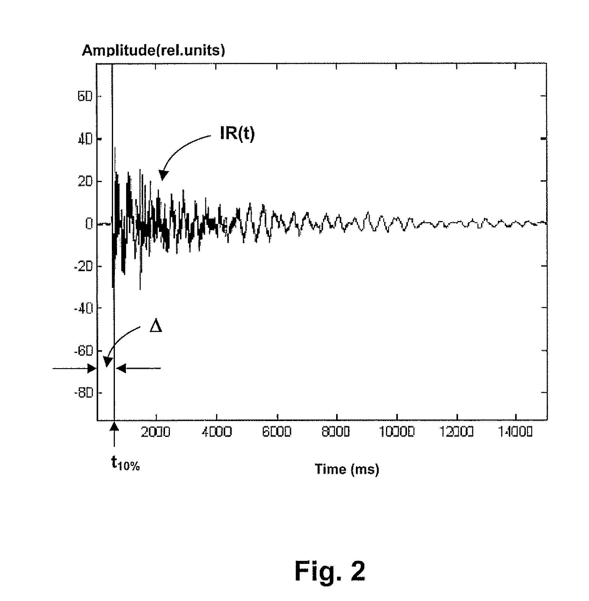
[0054]Based on the impulse response measuring technique described above, the erroneous distance matrix Merr shown in TABLE 4 has been obtained, the distances between loudspeakers 6 and 7 being in this example erroneously estimated due to the placement in an L-shaped room, where the direct propagation path between loudspeakers 6 ...

example 2

[0061]With reference to FIG. 4, the following example relates to a simulated five-loudspeaker set-up (a typical surround sound set-up comprising front left loudspeaker (L), front fight loudspeaker (R), centre loudspeaker (C) and the left and right surround loudspeakers LS and RS, respectively, the latter designated by reference numerals 16 and 17, respectively) in an L-shaped room 14. The surround loudspeakers 16 and 17 are placed on either side of protruding wall portions 15, which prevent direct sound propagation between the surround loudspeakers 16 and 17.

[0062]Referring to FIG. 5, there is shown a mapping of the loudspeakers of FIG. 4 obtained according to the invention with errors caused by the placement of the surround loudspeakers in the L-shaped room and with these errors removed by the application of the error correction method according to the invention. Specifically the correct positions of the loudspeakers are indicated by open circles (“without error”) and the erroneous...


PUM


Abstract

The invention relates to an automated estimation of the position (co-ordinates) of a set of loudspeakers in a room Based on measured impulse responses the distances between each pair of loudspeakers are estimated, thereby forming a distance matrix, and the resultant distance matrix is used by a multidimensional scaling (MDS) algorithm to estimate the co-ordinates of each individual loudspeaker An improved co-ordinate estimation can, if desired, be derived by utilising the stress values provided by the MDS algorithm.

Description

TECHNICAL FIELD[0001]The present invention relates to a method and system for determining the positions of sound-emitting transducers, such as loudspeakers, for instance in a listening room, one aim of this position estimation being to be able to carry out room corrections of the loudspeakers based on knowledge of the position of the loudspeakers in the room.BACKGROUND OF THE INVENTION[0002]Often there is a disparity between recommended, i.e. acoustically optimal, location of loudspeakers for an audio reproduction system and the locations of loudspeakers that are practically possible in a given environment. Restrictions on loudspeaker placement in a domestic environment typically occur due to room shape and furniture arrangement. Consequently, it may be desirable to modify signals from a pre-recorded media in order to improve on the staging and imaging characteristics of a system that has been configured incorrectly, i.e. to apply room correction means for instance in the form of di...

Claims


Application Information

Patent Timeline
IPC IPC(8): G01S3/80
CPCH04R5/02H04S7/301H04R2400/01H04R2205/024
Inventor CHOISEL, SYLVAINMARTIN, GEOFFREY GLENHLATKY, MICHAEL
Owner BANG & OLUFSEN
Learn More