
Motor drive

a motor drive and drive shaft technology, applied in the direction of power supply testing, capacitor testing, dynamo-electric converter control, etc., can solve the problems of sudden and significant drops in capacitance, dc link capacitor capacitance can change over time, and the capacitance decreases by a few percentage points, so as to minimise the relative error and minimise the cost function

Active Publication Date: 2021-09-16
GOODRICH CONTROL SYST LTD
View PDF0 Cites 0 Cited by
  • Summary
  • Abstract
  • Description
  • Claims
  • Application Information

AI Technical Summary

Benefits of technology

The patent describes a method for estimating a non-linear system model using a simple least squares estimator. The method involves identifying the non-linear function through a linearisation process and using a weighting function to minimize the cost function. The method also includes iterative processes to fit the model to the measured transfer function and determining a relative error function to account for measurement errors and system uncertainties. The technical effects of this patent include improved accuracy in estimating the system model and better accounting for measurement errors.

Problems solved by technology

However, the capacitance of the DC link capacitor can change over time.
One cause of this change in capacitance is a slow aging mechanism which leads to the capacitance decreasing by a few percentage points over a relatively long period of time, e.g. over a few years.
A further cause is a failure mechanism involving dielectric breakdown followed by capacitor self-healing, which can cause sudden and significant drops in the capacitance.
In order to minimise weight and volume, the minimal capacitance component possible is typically selected, however this generally means that there is little overvoltage margin and little current ripple margin in the design which makes premature aging of the device more likely.

Method used


Image

  • Motor drive
  • Motor drive

Examples


Embodiment Construction

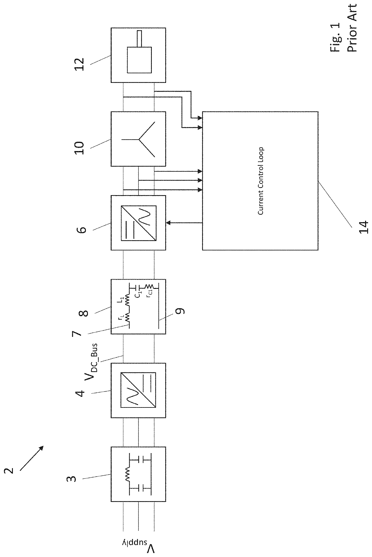
[0027]FIG. 1 is a schematic diagram of a prior art motor drive system 2. The motor drive system 2 includes a front-end rectifier 4 and a power inverter 6, which are connected by a DC bus 8.

[0028]The front-end rectifier 4 is arranged to receive an externally supplied AC voltage Vsupply, which in this example is a three-phase AC input voltage, via an electromagnetic compatibility (EMC) filter 3. The EMC filter 3 removes electromagnetic noise from the externally supplied AC voltage Vsupply and the conducted emissions from the system that can affect the external AC voltage.

[0029]The rectifier 4 converts this AC voltage Vsupply to a DC bus voltage VDC_Bus which is transferred to the inverter 6 across the DC bus 8, the details of which are discussed in more detail below. It will be appreciated that other arrangements are possible, e.g. in which the rectifier 4 receives a single-phase input. Thus the rectifier 4 is an AC-to-DC converter (ADC).

[0030]The inverter 6 takes the DC bus voltage V...


PUM


Abstract

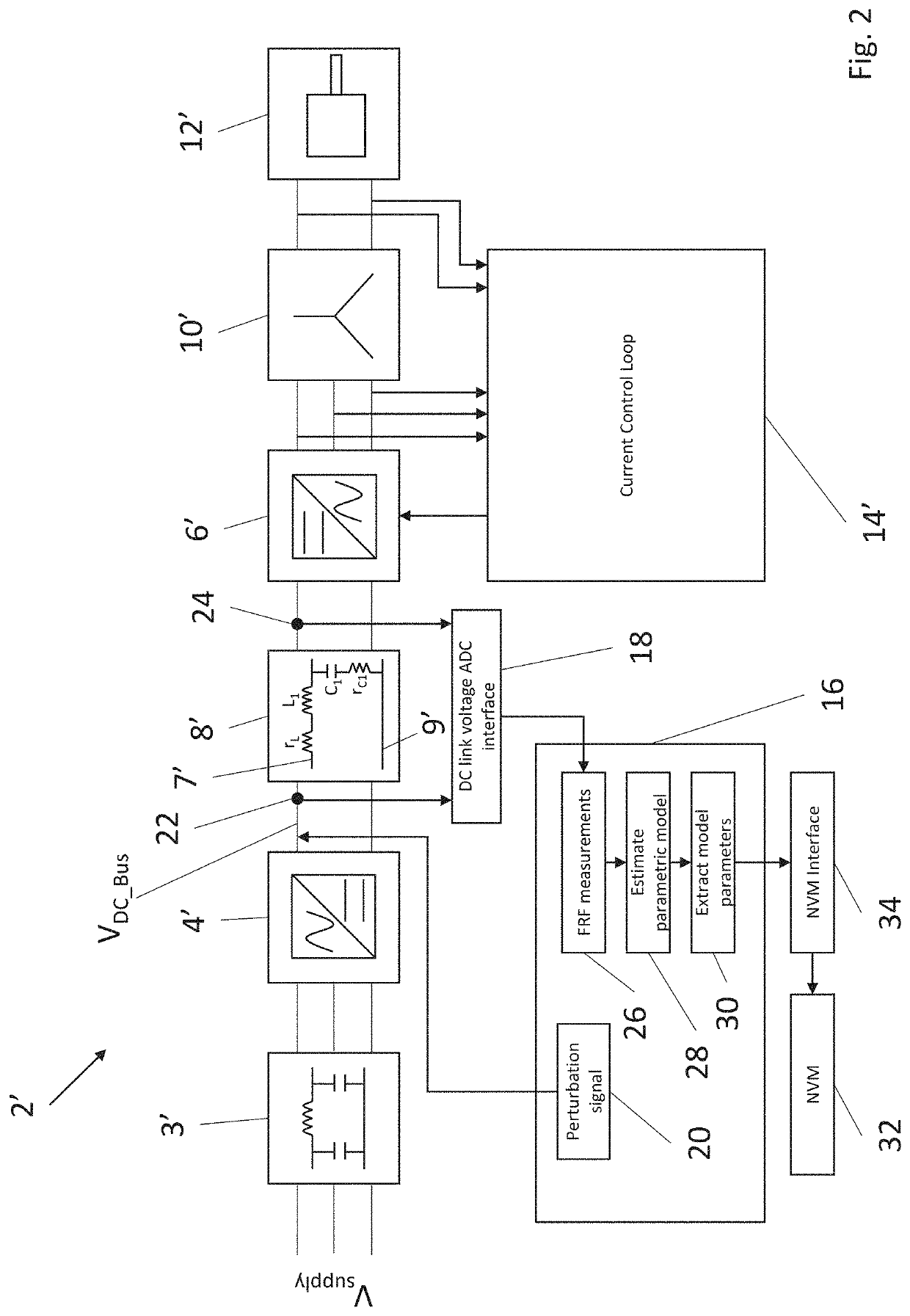
A motor drive comprises a rectifier arranged to receive an externally supplied AC voltage and to generate a DC bus voltage. An inverter is arranged to receive the DC bus voltage and to generate an AC output voltage for supply to an external load. A DC bus portion is connected between the rectifier and the inverter. The DC bus comprises first and second conductors, wherein an inductor is connected in series along the first conductor between the rectifier and the inverter. A DC link capacitor is connected in parallel between the conductors. A controller is arranged to supply a plurality of perturbation signals at a first node between the rectifier circuit portion and the DC bus portion, to measure a respective response signal at a second node between the DC bus and the inverter and is is arranged to generate a parameterised model of a transfer function of the DC.

Description

FOREIGN PRIORITY[0001]This application claims priority to European Patent Application No. 20275058.4 filed Mar. 13, 2020, the entire contents of which is incorporated herein by reference.TECHNICAL FIELD[0002]This disclosure relates to a motor drive arranged to monitor degradation of an internal capacitor, in particular the capacitance of a DC link capacitor of the motor drive.BACKGROUND ART[0003]Typical industrial motor drives include a front-end rectifier arranged to convert an externally supplied AC voltage to a rectified DC voltage, and a power inverter that converts this rectified DC voltage to an AC voltage suitable for supply to a motor. The motor may, in turn, drive an actuator. Such motor drives are used in a wide variety of applications, however some such motor drives are particularly applicable to aerospace applications.[0004]The front-end rectifier and the power inverter are generally separated by a DC bus, where the DC bus includes a DC link capacitor. The DC link capaci...

Claims


Application Information

Patent Timeline
Patent Type & Authority Applications(United States)
IPC IPC(8): H02P23/00H02P27/06
CPCH02P23/0022H02P2201/03H02P27/06H02M5/458G01R31/64G01R27/2605G01R31/42
Inventor MANN, JASPREET KAUR
Owner GOODRICH CONTROL SYST LTD
Learn More