Guideway switch apparatus for magnetically levitated vehicles

a technology of magnetically levitation and switch apparatus, which is applied in the direction of roads, transportation and packaging, construction, etc., can solve the problems of significant maintenance problem, significant obstacle to prt implementation, and significant wear of the accompanying wheel when the track is rolled on

Inactive Publication Date: 2010-08-12
SKYTRAN
View PDF21 Cites 15 Cited by
  • Summary
  • Abstract
  • Description
  • Claims
  • Application Information

AI Technical Summary

Problems solved by technology

However, the use of wheels as the primary method of suspending vehicles continues to pose a significant barrier to PRT implementation.
In addition, the unavoidable wear accompanying wheels rolling on tracks becomes a significant maintenance problem when a typical system might utilize thousands, or tens of thousands of vehicles.
Further, the use of wheels imposes a speed limitation on the vehicles.
Small, cheap wheels are generally not capable of even the speed range over which automobiles operate.
Wheels capable of that range of speed or higher become expensive and heavy, and their potential failure becomes a serious safety issue.
Thus, current PRT systems lack an economical, reliable and lightweight means to carry vehicles in slower speed, tight systems and faster, longer distance systems.
However, it is complicated and costly to construct switches that change the directions of vehicles traveling at any operational speed for the portion of network in which it is located.
However, the risk of a vehicle becoming detached and actually falling out of the guideway is an inherent problem of switches conventionally designed for underhanging vehicles.

Method used


Image

  • Guideway switch apparatus for magnetically levitated vehicles
  • Guideway switch apparatus for magnetically levitated vehicles
  • Guideway switch apparatus for magnetically levitated vehicles

Examples


Embodiment Construction

[0019]The following detailed description describes exemplary embodiments of the present invention. Although specific system configurations and flow diagrams are illustrated, it should be understood that the examples provided are not exhaustive and do not limit the present invention to the precise forms and embodiments disclosed. It will be apparent to one skilled in the art that the invention may be practiced without some or all of these specific details. In other instances, well-known process steps have not been described in detail in order not to unnecessarily obscure the invention.

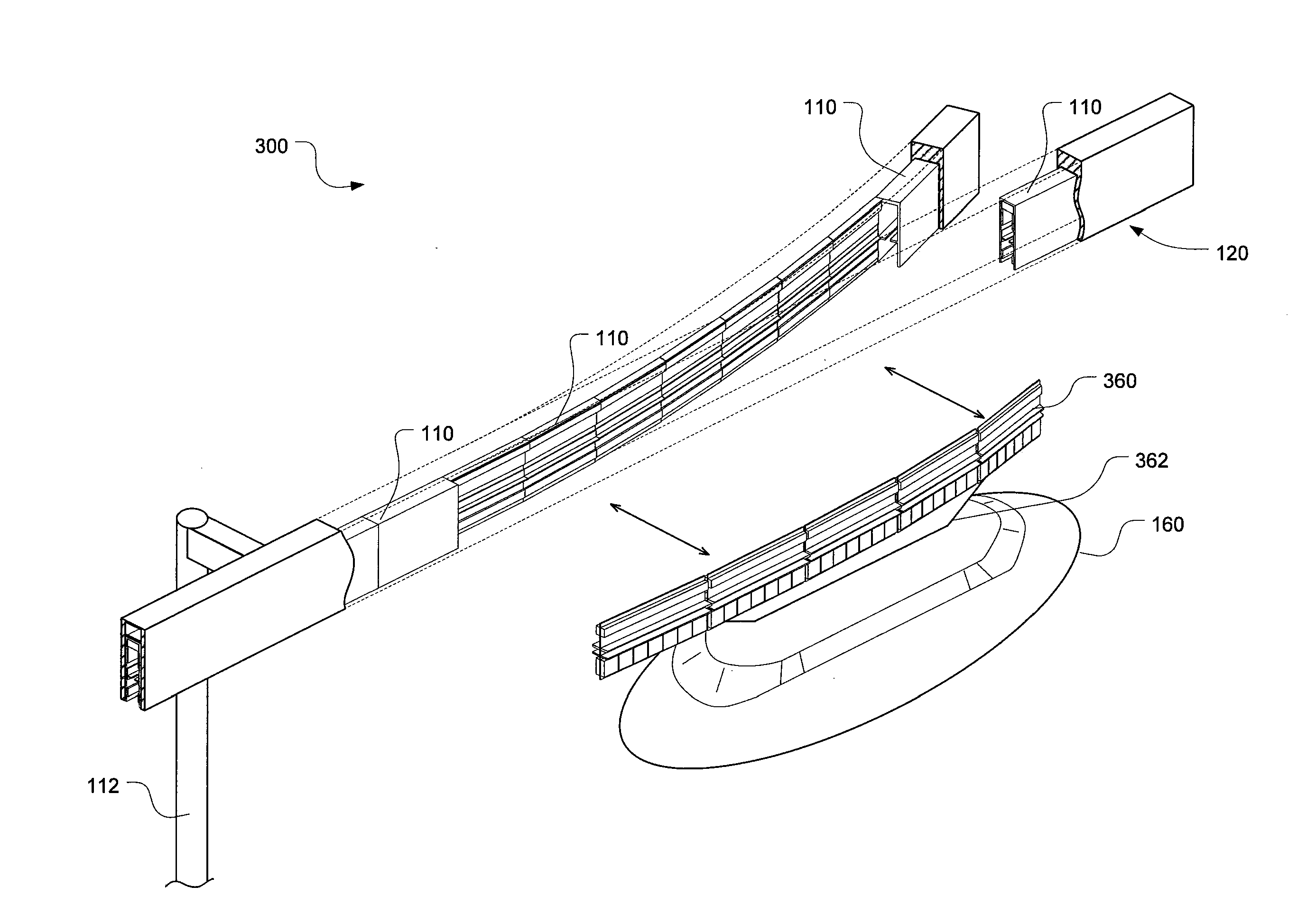
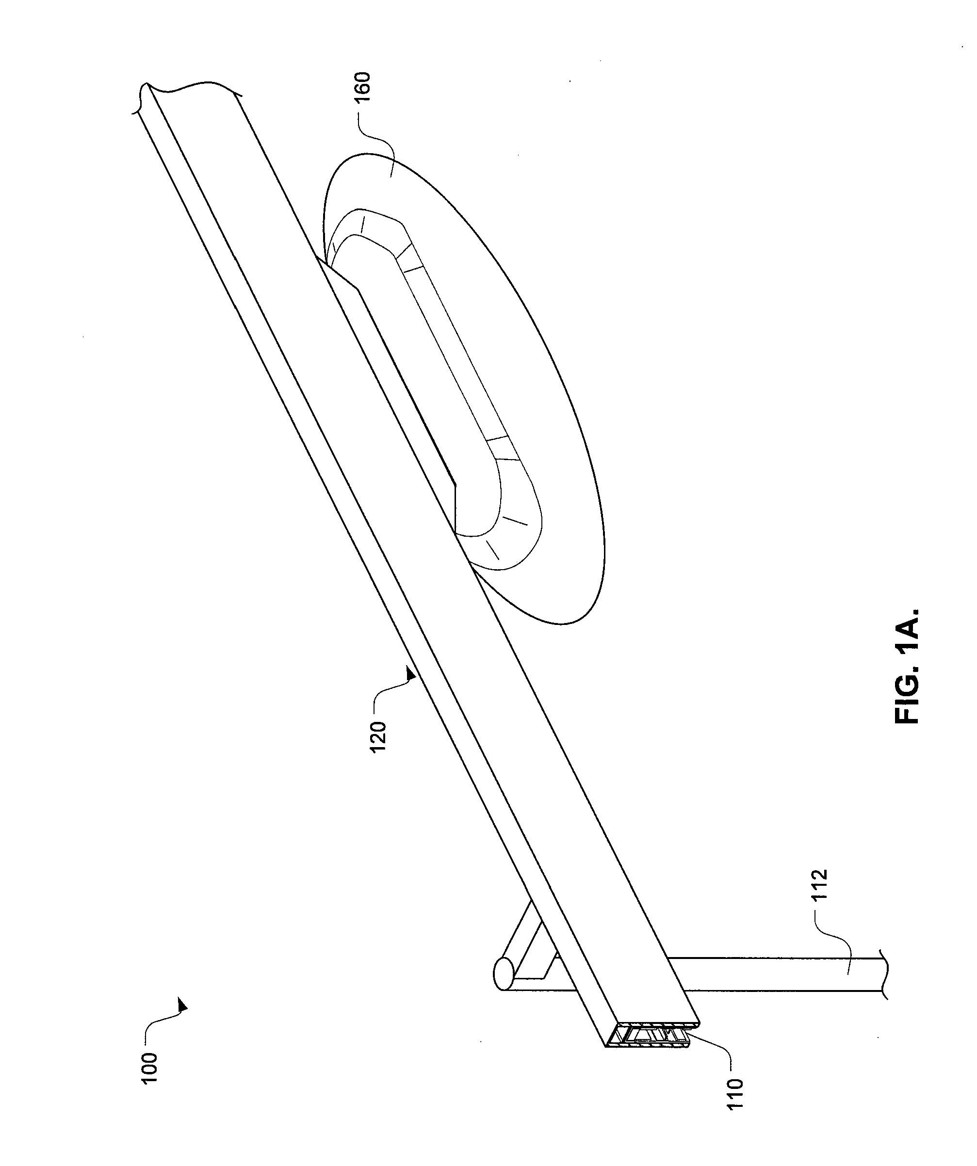
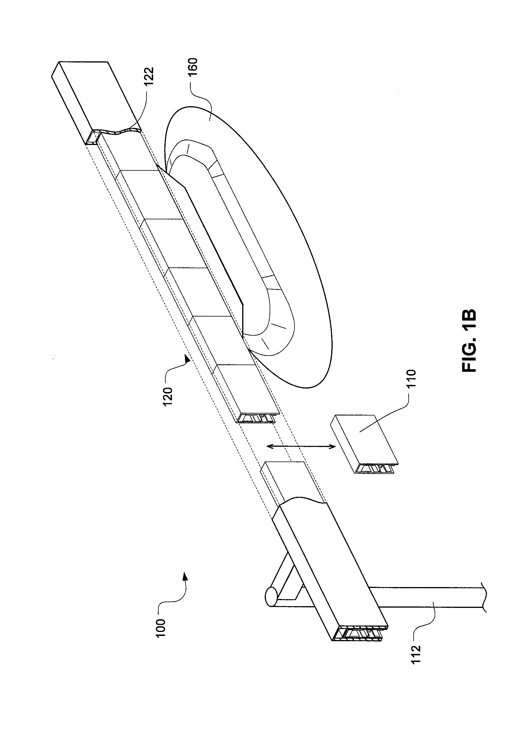
[0020]A method and system to integrate magnetic levitation technologies within a networked guideway transit system is provided. The magnetic levitation is used to replace wheels as the primary means of vehicle suspension and thus the automated transit systems (e.g., PRT system) can be made commercially and economically feasible. More specifically, a method and system use permanent magnet repulsion with ...


PUM


Abstract

A switch is used, at the divergent zone, to cause the vehicle bogie to follow one path or the other in the guideway. This is accomplished by substituting an attracting magnetic array on the side that the vehicle bogie is desired to follow. The switch may operate without moving parts, so there is no inertial penalty to limit operational frequency. The switch is designed to fail gracefully in the absence of activation power or control signals. Further, the switch is designed to ensure that there would be no derailment or dropping of a vehicle.

Description

CROSS-REFERENCES TO RELATED APPLICATIONS[0001]The present application claims benefit to U.S. Provisional Patent Application No. 60 / 870,884, filed Dec. 20, 2006, the complete disclosure of which is incorporated herein by reference.BACKGROUND OF THE INVENTION[0002]The present invention is directed to transportation or transit systems, and more specifically, to networked guideway transit systems designed to enable the movement of large numbers of passengers or parcels in a flexible manner.[0003]Guideway-based transportation systems have been used to transport people or goods. One example is a “Personal Rapid Transit” (PRT) system. In the PRT system, each vehicle carries just one party or small group (or payload) from their origin directly to their destination, starting at a time determined by the party's arrival at its origin. Vehicles are typically piloted by computer and move non-stop along guideways with diverging and merging paths. At origin and destination access points (termed “p...

Claims


Application Information

Patent Timeline
Patent Type & Authority Applications(United States)
IPC IPC(8): E01B25/34
CPCE01B25/26
Inventor WAMBLE, JOHN LEE
Owner SKYTRAN
Why Eureka
Try Eureka