
Cable suspended, self leveling tram with self-propelled tractor bogie

a self-leveling, tram technology, applied in the direction of railways, rope railways, trains, etc., can solve the problem that the amount of the load is not disclosed, and achieve the effect of smooth ride, smooth ride, and efficient way to span long distances

Inactive Publication Date: 2009-12-01
MORRIS RICHARD DAVID
View PDF12 Cites 44 Cited by
  • Summary
  • Abstract
  • Description
  • Claims
  • Application Information

AI Technical Summary

Benefits of technology

Enables economical and high-speed transportation of people or goods by reducing vertical acceleration forces and eliminating the need for costly rail structures, providing a smoother and faster ride over varied terrain.

Problems solved by technology

Serge does not disclose what would eliminate the vertical acceleration forces associated with high speed travel on a cantenary cableway.

Method used


Image

  • Cable suspended, self leveling tram with self-propelled tractor bogie
  • Cable suspended, self leveling tram with self-propelled tractor bogie
  • Cable suspended, self leveling tram with self-propelled tractor bogie

Examples


Embodiment Construction

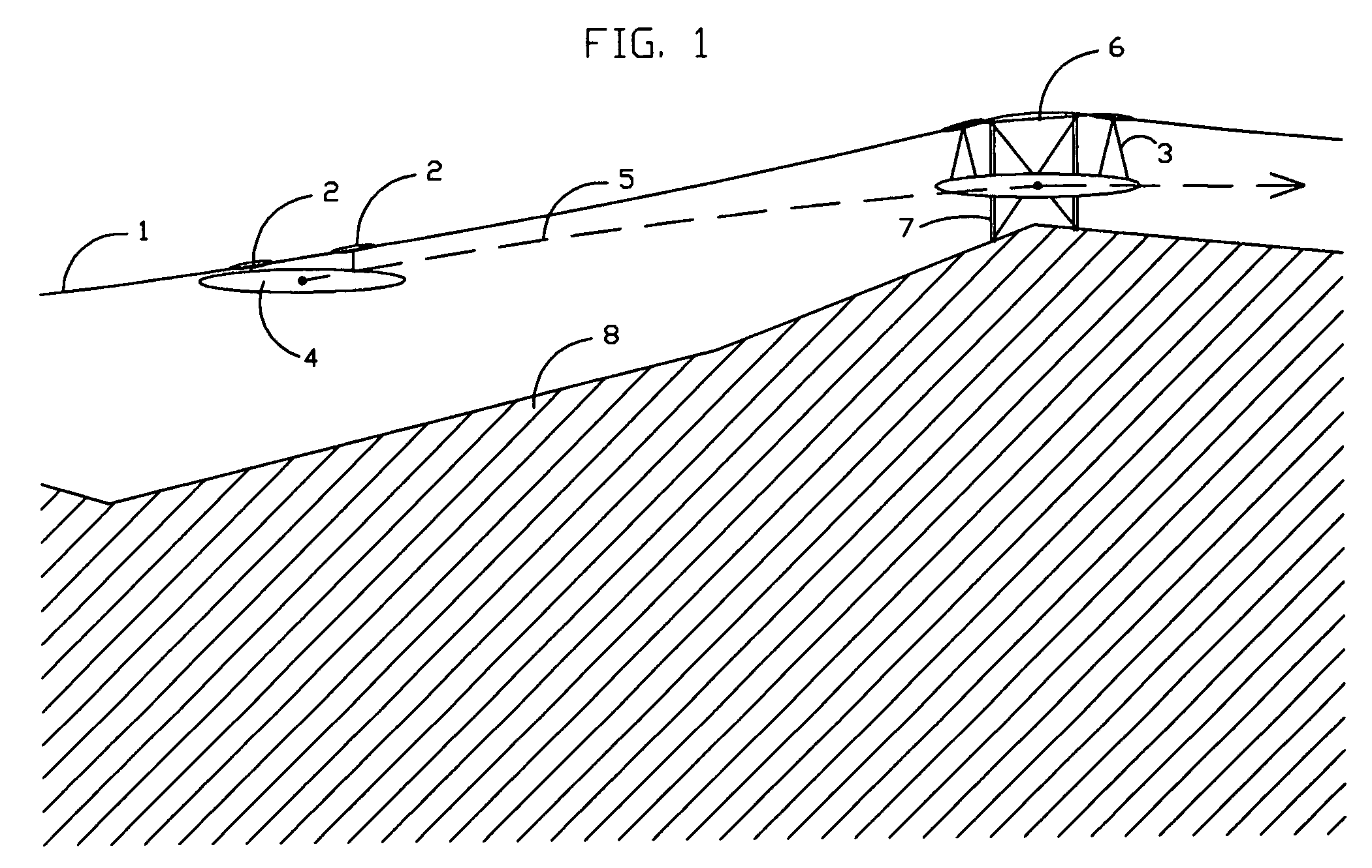
[0057]A cableway with suspended trolley and remote tractor bogie is illustrated in FIG. 1. The cantenary cableway 1, is supported by a curved rail 6, designed to provide a radius of curvature from the upward slope approaching the support tower 7, to the downward slope of the cableway. A tram 4, is supported by adjusting cables 3, and pulled along the cableway by any number of self-propelled bogies 2. The resulting path 5, is accomplished by the aforementioned mechanics over the varied terrain 8.

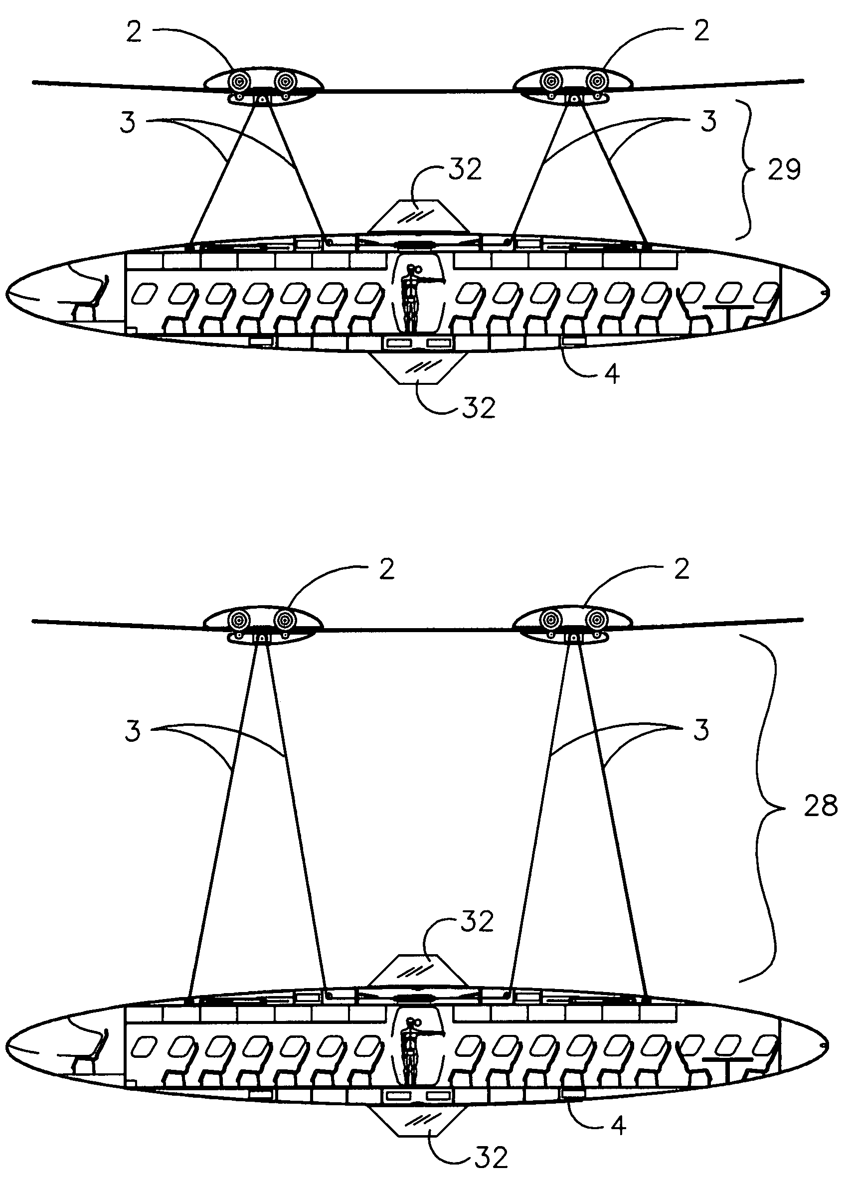
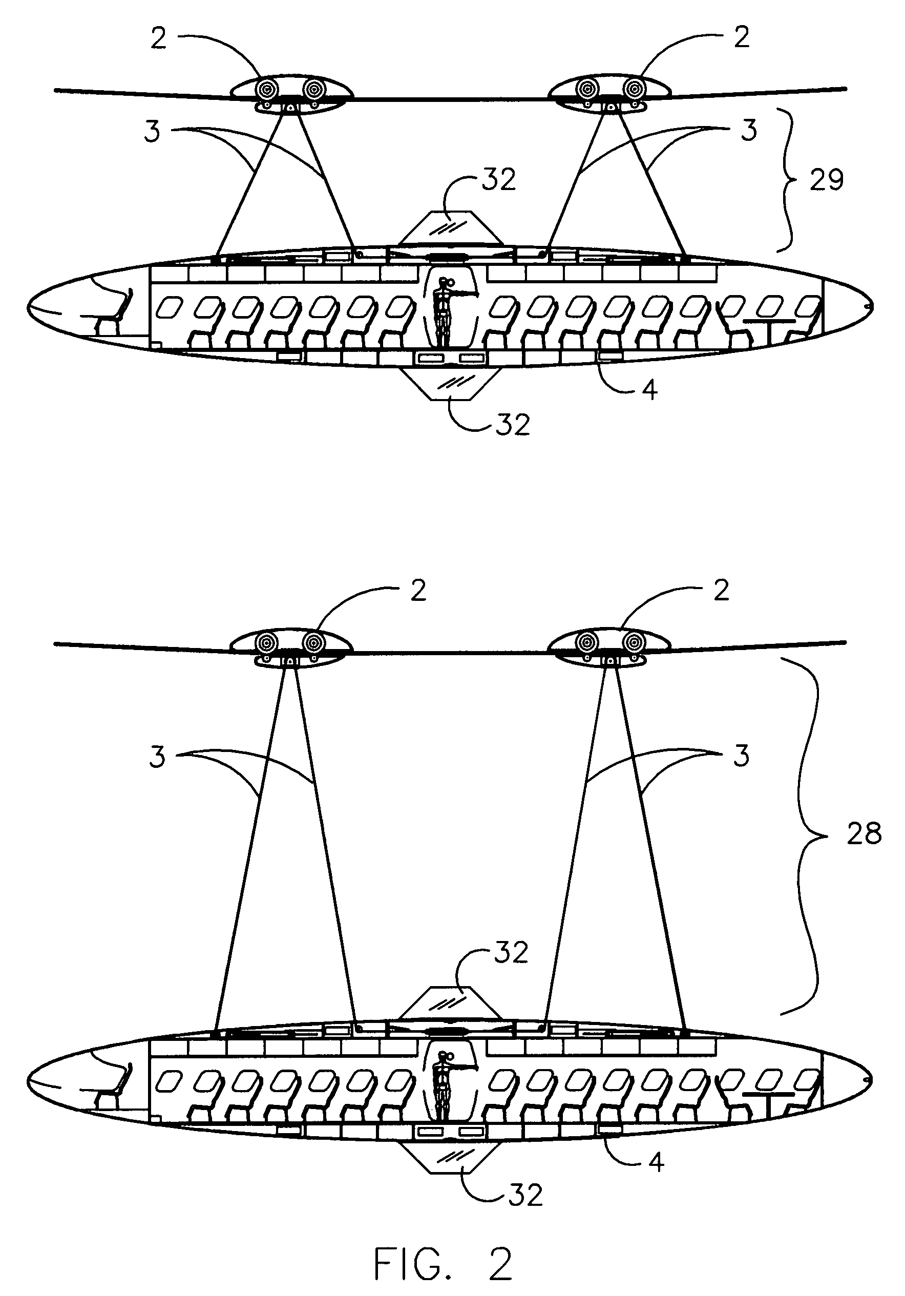
[0058]FIG. 2 shows a section / elevation of the tram 4, suspended by adjustable cable 3, and pulled by the bogie / trolley 2. This drawing illustrates the dynamic range of adjustment capable by the cable 3. Typically the tram pulls the cable in 29, at low points on the cableway and lets cable out 28, when approaching a high point along the route. Vertical fins 32, are added to counter act the crosswind forces and keep the tram centered under the cableway.

[0059]FIG. 3 is a sectional view of the tr...


PUM


Abstract

A cableway with suspended tram and remote bogie is disclosed. This includes a self-contained motor, traction and support sheaves with provision for adjusting the height of the tram below said cable for limiting vertical acceleration caused by travel along the cantenary curve of the cableway.

Description

BACKGROUND OF THE INVENTION[0001]1. Field of the Invention[0002]The present invention relates generally to a cable suspended tram with self-leveling car and remote tractor unit used primarily for the movement of people or goods at lower cost and higher speeds than current designs.[0003]2. Description of the Prior Art[0004]It is advantageous to use, cable structures to traverse rugged or congested terrain. Cable structures have been used to pull the tram in a close loop such as a chairlift or enable the use of an on board tractor drive system.[0005]U.S. Pat. No. 2,198,536 issued to Fredrik Johnsen on Dec. 14, 1938 teaches us one method of ramping on to a support rail from a cableway but fails to show us how a capstan or containment roller would traverse the underside of the support rail.[0006]U.S. Pat. No. 3,353,503 issued to Frank P. Pettit on Nov. 21, 1967 shows us a containment roller but no method of minimizing the vertical acceleration caused by the cantenary curve.[0007]U.S. Pa...

Claims


Application Information

Patent Timeline
Patent Type & Authority Patents(United States)
IPC IPC(8): B61B7/00
CPCE01B25/16B61B7/06
Inventor MORRIS, RICHARD DAVID
Owner MORRIS RICHARD DAVID
Learn More