Device with flat-sided outlet for controlling anesthetic flow

a technology of anesthetic flow and a flat-sided outlet, which is applied in the direction of liquid handling, packaging goods type, drug compositions, etc., can solve the problems of high cost of anesthetics and failure to effectively minimize the release of anesthetics, and achieve the effect of effectively minimizing the release of liquid to the surrounding environmen

Active Publication Date: 2010-08-12
PIRAMAL CRITICAL CARE INC
View PDF48 Cites 14 Cited by
  • Summary
  • Abstract
  • Description
  • Claims
  • Application Information

AI Technical Summary

Benefits of technology

[0005]This application discloses an apparatus and system for transferring a liquid, such as an anesthetic, from a reservoir to a machine while effectively minimizing the release of the liquid to the surrounding environment. A apparatus can include a first component having a base and a nozzle, the base being configured so as to be capable of being sealed and affixed to an opening of a reservoir, the nozzle being externally threaded, and wherein a through-hole extends through the base and the nozzle, a second component having an aperture defined by an inner surface of the second component, wherein a portion of an exterior surface of the second component that mates with a vaporizer has a polygonal shape with three or more flat sides, and wherein the aperture has internal threads for engaging with the external threads of the nozzle, a support member extending into the aperture from the inner surface, a protrusion extending from the support member toward the internal threads, wherein the protrusion is configured to be capable of sealing the through-hole in the nozzle, wherein a fluid in the reservoir may exit the reservoir by way of the through-hole and the aperture; and wherein twisting the first component and second component relative to each other causes the protrusion to seal or unseal the through-hole thereby allowing or preventing the flow of fluid.

Problems solved by technology

Since it is unwise to expose medical personnel performing the procedure to the anesthetic, and since anesthetics are expensive, devices have been developed to minimize the release of the anesthetic from the bottle to the environment surrounding the vaporizer to the environment surrounding a vaporizer.
These devices, however, have failed to effectively minimize the release of anesthetic.

Method used


Image

  • Device with flat-sided outlet for controlling anesthetic flow
  • Device with flat-sided outlet for controlling anesthetic flow
  • Device with flat-sided outlet for controlling anesthetic flow

Examples


Embodiment Construction

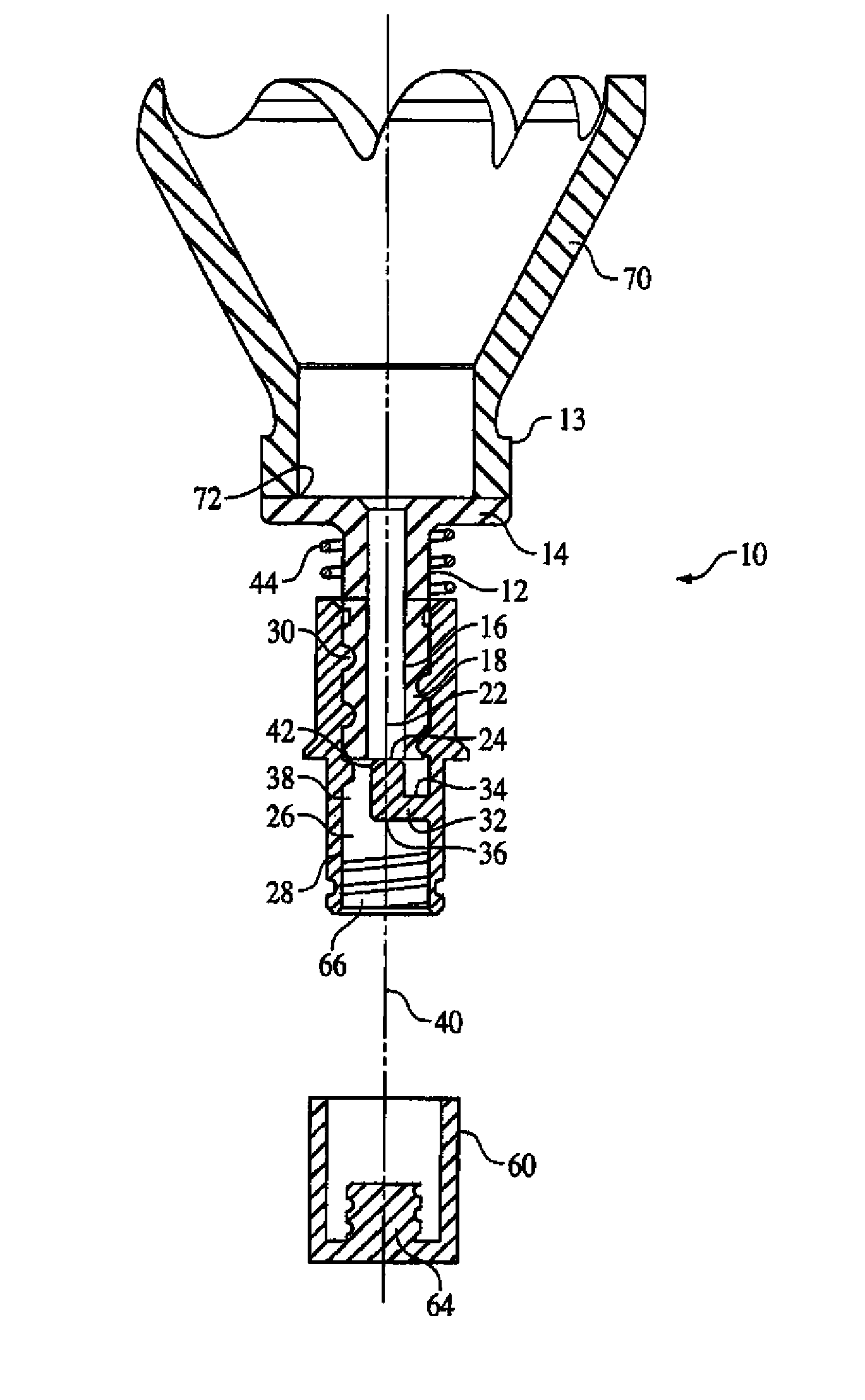
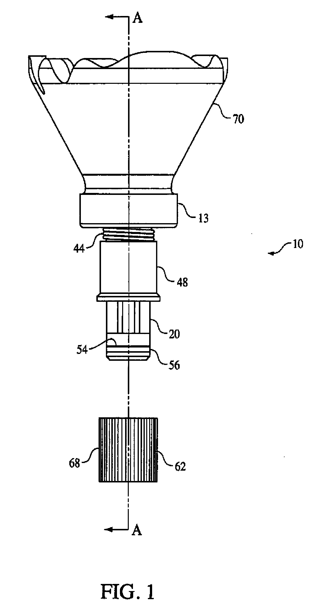
[0019]The accompanying drawings are intended to provide further understanding of the invention and are incorporated in and constitute a part of the description of the invention. The drawings illustrate an embodiment of the invention and together with the description illustrate principles of the invention.

[0020]The drawings should not be taken as implying any necessary limitation on the essential scope of invention. The drawings are given by way of non-limitative example to explain the nature of the invention.

[0021]For a more complete understanding of the instant invention reference is now made to the following description taken in conjunction with accompanying drawings.

[0022]The various features of novelty which characterize the invention are pointed out specifically in the claims which are a part of this description. For a better understanding of the invention, reference should be made to the drawings and descriptive matter in which there are illustrated and described preferred emb...


PUM

PropertyMeasurementUnit
shapeaaaaaaaaaa
boiling pointsaaaaaaaaaa
vapor pressureaaaaaaaaaa

Abstract

An apparatus and system for transferring a liquid, such as an anesthetic, from a reservoir to a machine while effectively minimizing the release of the liquid to the surrounding environment. The apparatus can include a first and a second component wherein twisting the first component and second component relative to each other causes a protrusion to seal or unseal a through-hole thereby allowing or preventing the flow of fluid and wherein a portion of an exterior surface of the second component that mates with a vaporizer has a polygonal shape with three or more flat sides.

Description

CROSS-REFERENCE TO RELATED APPLICATION[0001]This application claims the benefit under 35 U.S.C. §119(e) of the earlier filing date of U.S. Provisional Application Ser. No. 61 / 110,417 filed on Oct. 31, 2008, the entire disclosure of which is hereby incorporated by reference herein as if being set forth in its entirety.FIELD OF INVENTION[0002]This application discloses an invention which is related, generally and in various embodiments, to a device for supplying a liquid to a machine, such as a vaporizer.BACKGROUND OF THE INVENTION[0003]Liquid anesthetics are often packaged in glass bottles and shipped to a location where they may be used to anesthetize a patient, who is undergoing a medical or dental procedure. Such anesthetics may also be used to induce analgesia in a patient who is undergoing a medical or dental procedure. In order to administer the anesthetic, the contents of the glass bottle are placed in a vaporizer. The vaporizer may be used to vaporize the anesthetic, and prov...

Claims


Application Information

Patent Timeline
Patent Type & Authority Applications(United States)
IPC IPC(8): A61M16/18A61M16/10
CPCA61M16/183B65D83/00A61M2205/6045A61P17/02
Inventor CUZYLDO, MICHAELIDE, MICHAEL
Owner PIRAMAL CRITICAL CARE INC
Why Eureka
Try Eureka