Methods for attaching carbon nanotubes to a carbon substrate

a carbon nanotube and substrate technology, applied in the direction of cell components, lighting and heating apparatus, physical/chemical process catalysts, etc., can solve the problems of reducing the overall resistance, limiting the design factor, and limiting the reliability and functionality of these contacts, so as to reduce the thermal (or electrical) interface resistance

Active Publication Date: 2010-08-12
PURDUE RES FOUND INC
View PDF99 Cites 36 Cited by
  • Summary
  • Abstract
  • Description
  • Claims
  • Application Information

AI Technical Summary

Benefits of technology

[0007]One embodiment of the present invention is an apparatus used to reduce the thermal (or electrical) interface resistance between two connecting devices such as an electronic component and a heat sink, or between one electrical component and another electrical component.
[0008]The invention in one embodiment includes synthesizing CNT arrays on one or both sides of thin and highly compliant ‘foil’ substrates comprised of interwoven or dry adhered CNTs and / or graphite and / or other carbon-based materials. These free-standing, carbon-based substrates can be purchased commercially or fabricated through processes that are defined in the open literature. Carbon materials such as CNTs and graphite are compliant and have high axial and in-plane thermal conductivities. Because of such properties, carbon-based foil substrates combined with CNT arrays grown on one or both sides creates an apparatus that is effective in spreading heat and providing low interface resistance. The carbon-carbon interface between a CNT and the carbon-based substrate promotes efficient heat transfer and adhesion due to a gradient chemical and morphological structure.

Problems solved by technology

Reliability and functionality of these contacts can often be a limiting design factor.
A major portion of electrical contact resistance comes from the lack of ideal mating between surfaces.
Primary causes of this problem involve the mechanical properties of the surfaces and surface roughness.
The use of an individual MWCNT or SWCNT may not be sufficient to reduce contact resistance at an interface significantly.
However, by using an array of SWCNTs or MWCNTs as an interfacial layer, it is expected that numerous individual contact spots and contact area enlargement can create current flow paths through each contact, thus reducing overall resistance.

Method used


Image

  • Methods for attaching carbon nanotubes to a carbon substrate
  • Methods for attaching carbon nanotubes to a carbon substrate
  • Methods for attaching carbon nanotubes to a carbon substrate

Examples


Embodiment Construction

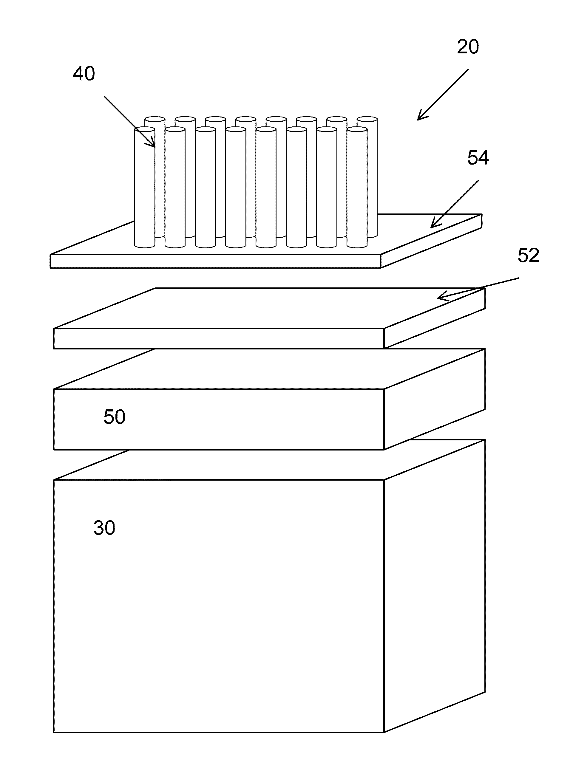
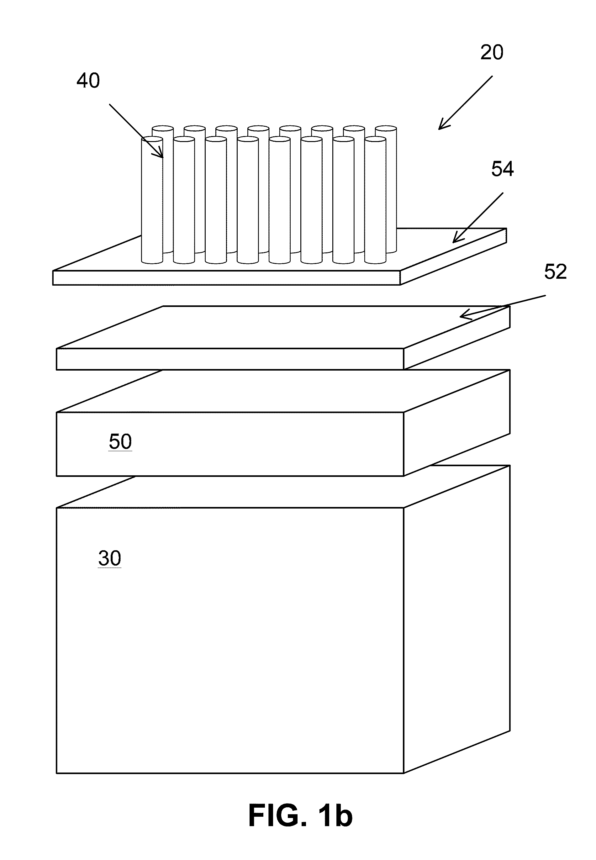
[0042]For the purposes of promoting an understanding of the principles of the invention, reference will now be made to the embodiments illustrated in the drawings and specific language will be used to describe the same. It will nevertheless be understood that no limitation of the scope of the invention is thereby intended, such alterations and further modifications in the illustrated device, and such further applications of the principles of the invention as illustrated therein being contemplated as would normally occur to one skilled in the art to which the invention relates. At least one embodiment of the present invention will be described and shown, and this application may show and / or describe other embodiments of the present invention. It is understood that any reference to “the invention” is a reference to an embodiment of a family of inventions, with no single embodiment including an apparatus, process, or composition that must be included in all embodiments, unless otherwis...


PUM

PropertyMeasurementUnit
thicknessaaaaaaaaaa
thicknessaaaaaaaaaa
pressureaaaaaaaaaa

Abstract

Vertically oriented carbon nanotubes (CNT) arrays have been simultaneously synthesized at relatively low growth temperatures (i.e., <700° C.) on both sides of aluminum foil via plasma enhanced chemical vapor deposition. The resulting CNT arrays were highly dense, and the average CNT diameter in the arrays was approximately 10 nm, A CNT TIM that consist of CNT arrays directly and simultaneously synthesized on both sides of various types of foil has been fabricated. The TIM is insertable and allows temperature sensitive and / or rough substrates to be interfaced by highly conductive and conformable CNT arrays. The use of foil, including substrates fabricated from carbon (CNT woven arrays, exfoliated graphite sheets, bucky paper, and the like) is disclosed.

Description

CROSS-REFERENCE TO RELATED APPLICATIONS[0001]This application is a continuation-in-part of U.S. patent application Ser. No. 11 / 873,952, filed Oct. 17, 2007, entitled ELECTROTHERMAL INTERFACE MATERIAL ENHANCER and claims the benefit of priority to U.S. Provisional Patent Application Ser. No. 61 / 144,915, filed Jan. 15, 2009, entitled METHODS FOR ATTACHED CARBON NANOTUBES TO A CARBON SUBSTRATE, both of which are incorporated herein by reference.FIELD OF THE INVENTION[0002]This invention pertains to flexible structures having nanostructures attached to a surface, and in particular to a thermal interface including a carbon substrate.BACKGROUND OF THE INVENTION[0003]Electrical and thermal contacts are elements in many engineering systems and applications at the macro, micro, and nano scales. Reliability and functionality of these contacts can often be a limiting design factor. A major portion of electrical contact resistance comes from the lack of ideal mating between surfaces. Primary ca...

Claims


Application Information

Patent Timeline
Patent Type & Authority Applications(United States)
IPC IPC(8): F28F7/00B23P11/00B32B33/00
CPCB01J23/745Y10T29/49826B01J37/0244B82Y10/00B82Y30/00B82Y40/00C01B31/0226C01B31/0233C01B2202/08H01L51/0048H01L51/102H01M4/8605H01M4/8807Y02E60/50B01J37/0238C01B32/16C01B32/162Y10T428/23943H10K85/221H10K10/82
Inventor COLA, BARATUNDE A.FISHER, TIMOTHY S.
Owner PURDUE RES FOUND INC
Why Eureka
Try Eureka