Connection line used for stator of electric motor, stator including that connection line, and method for bending the connection line

US20100201212A1Active Publication Date: 2010-08-12TOYOTA JIDOSHA KK

Image

  • Connection line used for stator of electric motor, stator including that connection line, and method for bending the connection line
  • Connection line used for stator of electric motor, stator including that connection line, and method for bending the connection line
  • Connection line used for stator of electric motor, stator including that connection line, and method for bending the connection line

Examples


Embodiment Construction

[0021]Hereinafter reference will be made to the drawings to describe the present invention in embodiments. In the following description, identical components are identically denoted. Their names and functions are also identical. Accordingly, they will not be described repeatedly in detail.

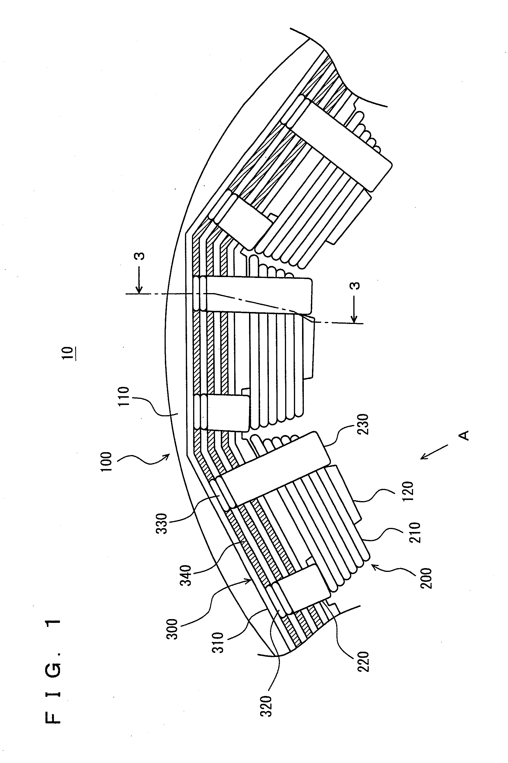
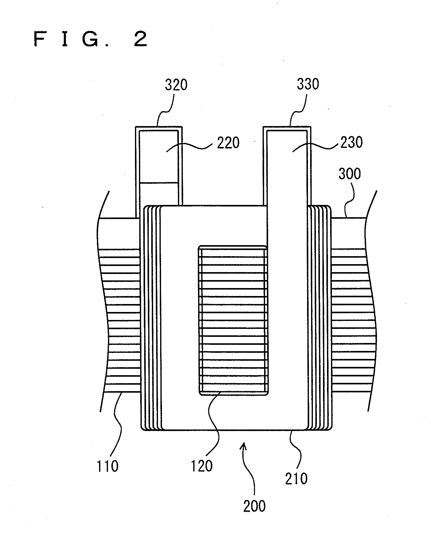
[0022]With reference to FIGS. 1, 2, the present invention in an embodiment provides a stator 10 for an electric motor. FIG. 1 is a partial plan view of stator 10, as seen downward. FIG. 2 is a partial plan view of stator 10, as seen in a direction A indicated in FIG. 1. Stator 10 includes a stator core 100, a coil 200, and a bus bar 300.

[0023]Stator core 100 is formed of a plurality of magnetic steel plates stacked in layers. Stator core 100 has a main body 110 and teeth 120. The stator's main body 110 is formed in a ring (or a hollowed cylinder) uniform in width along its entire circumference. A plurality of teeth 120 are provided on an inner circumferential surface of the stator's main body 110 w...


PUM

PropertyMeasurementUnit
Lengthaaaaaaaaaa

Abstract

A connection line has a first bent portion bent toward a coil's main body in a vicinity of a stator core's axial length limit line. Furthermore, the connection line at a portion closer to the coil's main body than the first bent portion has a second bent portion bent away from the coil's main body. Furthermore, the connection line has a third bent portion bent away from the coil's main body to have a connection portion along an end surface of the terminal member in contact therewith generally parallel thereto.

Description

TECHNICAL FIELD[0001]The present invention relates generally to connection lines used for stators of electric motors, and particularly to connection lines connecting a coil wound on a stator core to a terminal member provided radially outer than the coil as seen from the center of the core.BACKGROUND ART[0002]An electric motor used as a source for driving an electric vehicle or the like normally has a stator core in the form of a ring having a plurality of radially inwardly projecting teeth circumferentially with fixed intervals. The stator core has each tooth with a coil wound thereon. Such stator is fabricated by previously winding a coil in accordance with each tooth's geometry to provide a unit of coil and fitting each unit of coil on a tooth to facilitate assembling the stator. This, however, requires that after each unit of coil is fit on a tooth, predetermined coils be electrically connected together, and the operation connecting them together is cumbersome. This problem is r...

Claims


Application Information

Patent Timeline
12 Aug 2010
Publication
US20100201212A1
IPC
H02K11/00; H02K15/04
CPC
H02K3/18; Y10T29/49009; H02K15/0075; H02K3/522; H02K15/0068
Inventors
URANO, HIROAKI; TATEMATSU, KAZUTAKA