Wide angle optical system and image pickup apparatus using the same

Active Publication Date: 2010-08-12
OM DIGITAL SOLUTIONS CORP
View PDF4 Cites 27 Cited by
  • Summary
  • Abstract
  • Description
  • Claims
  • Application Information

AI Technical Summary

Benefits of technology

[0016]With the above-described arrangement, it is possible to realize a compact and high optical performance wide angle optical system with a small number of lenses for which various aberrations can be corrected easily.
[0017]Preferably, in a wide angle optical system according to the present invention as defined above, the cemented doublet of a biconcave lens and a biconvex lens arranged in the above-mentioned order from the objec

Problems solved by technology

It is difficult to design an optical system for a lens with a small number of component lenses, while securi

Method used


Image

  • Wide angle optical system and image pickup apparatus using the same
  • Wide angle optical system and image pickup apparatus using the same
  • Wide angle optical system and image pickup apparatus using the same

Examples


Embodiment Construction

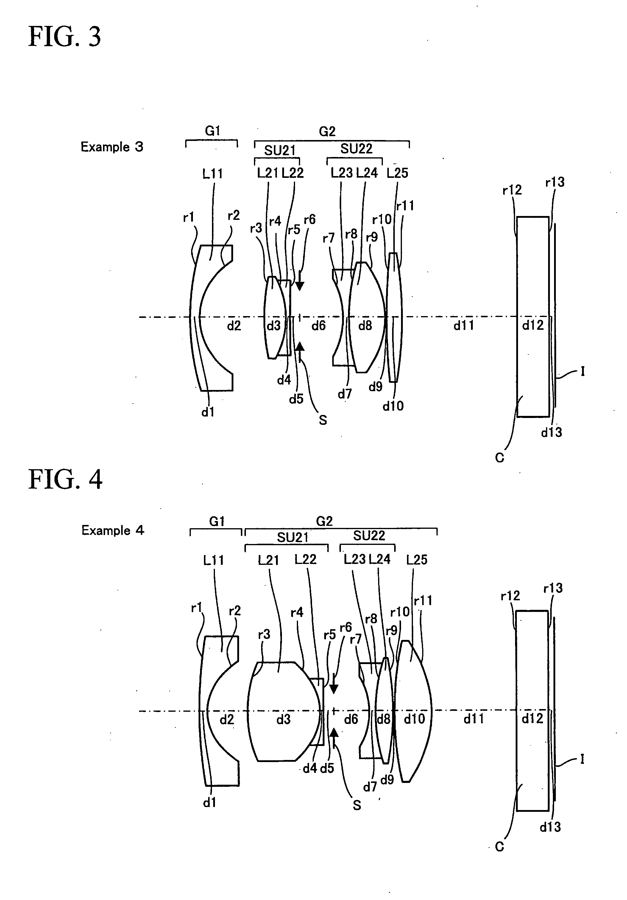
[0076]Now, optical systems of Examples 1 through 4 according to the present invention will be described below.

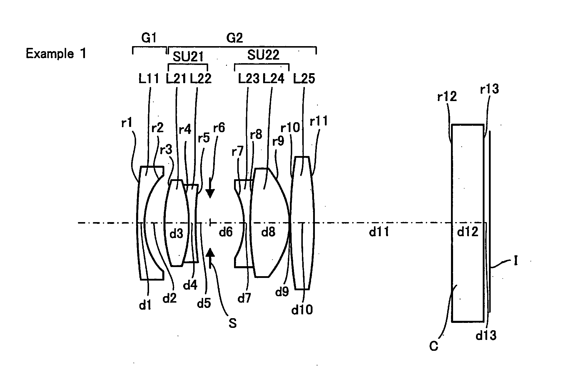
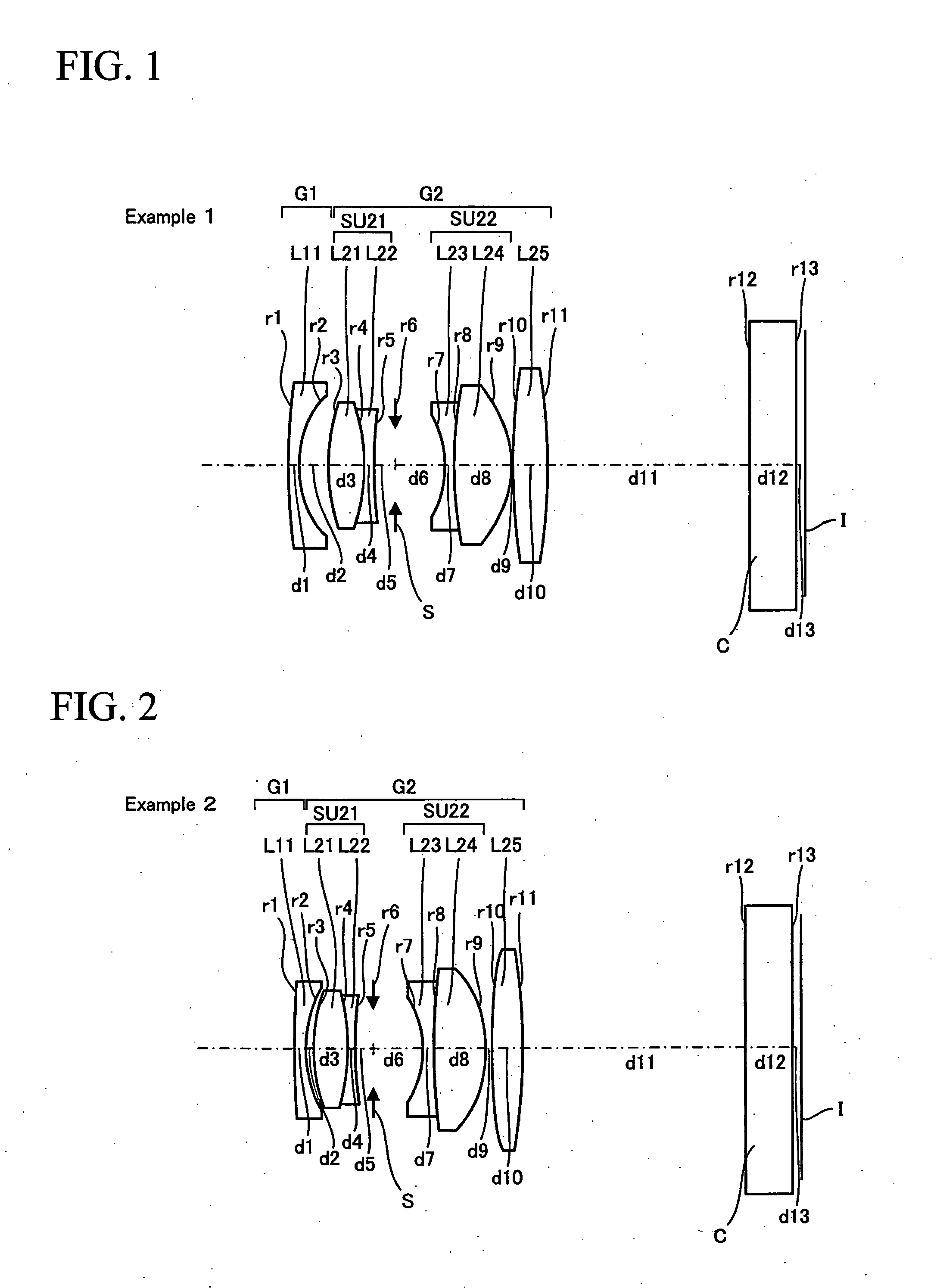
[0077]FIG. 1 is a schematic cross-sectional view of the optical system of Example 1.

[0078]As shown in FIG. 1, the wide angle optical system of Example 1 includes a first lens group G1 having negative refractive power and a second lens group G2 having positive refractive power arranged from the object side in the above-mentioned order.

[0079]The first lens group G1 is formed by a negative meniscus lens L11 with its convex surfaces directed to the object side.

[0080]The second lens group G2 is formed by sequentially arranging a cemented lens SU21 of a biconvex positive lens L21 and a biconcave negative lens L22, an aperture diaphragm S, a cemented lens SU22 of a biconcave negative lens L23 and a biconvex positive lens L24 and a single biconvex positive lens L25 from the object side. In FIG. 1, C denotes a cover glass and I denotes an image plane.

[0081]Two surfaces including the ...


PUM


Abstract

A wide angle optical system includes:
    • a first lens group of negative refractive power; and
    • a second lens group of positive refractive power;
    • the first lens group and the second lens group being arranged in the above-mentioned order from the object side;
    • the second lens group including:
    • a cemented doublet SU21;
    • an aperture diaphragm;
    • a lens SU22; and
    • a biconvex lens L25;
    • the cemented doublet, the aperture diaphragm, the lens and the biconvex lens being arranged in the above-mentioned order from the object side;
    • the largest ones of the air spaces on the axis being the front and rear spaces of the aperture diaphragm except the back focal length;
    • the wide angle optical system being divided into the first lens group and the second lens group at the second largest air space operating as a boundary.

Description

CROSS REFERENCE TO RELATED APPLICATION[0001]This application claims the benefit of Japanese Patent Application No. 2009-029563 filed in Japan on Feb. 12, 2009, the contents of which are incorporated herein by reference.BACKGROUND OF THE INVENTION[0002]1. Field of the Invention[0003]The present invention relates to an optical system that is used in an image pickup apparatus or the like. More particularly, the present invention relates to a wide angle optical system that is used in a digital single lens camera or a compact camera and also to an image pickup apparatus using the same.[0004]2. Description of the Related Art[0005]Wide angle lenses of digital cameras require an optical system having a long back focal length because they need a space for receiving optical elements including a filter immediately in front of the electronic imaging plane, while securing a wide angle of view. Retrofocus type optical systems having a front lens group of negative refractive power and a back lens ...

Claims


Application Information

Patent Timeline
IPC IPC(8): G03B13/34G02B13/04H04N5/262
CPCG02B13/06G02B13/00G03B13/34G02B13/16
Inventor YAMADA, YASUHARUKIMATA, HIROHIKO
Owner OM DIGITAL SOLUTIONS CORP
Why Eureka
Try Eureka