Cabinet structure for display apparatus

a technology for display apparatuses and cabinets, applied in the field of cabinet structure for display apparatuses, can solve the problems of warp or flexure in front cabinets, vibration noise, gap between cabinets, etc., and achieve the effect of preventing vibration noise, preventing warp or flexure, and ensuring the appearan

Inactive Publication Date: 2010-08-12
FUNAI ELECTRIC CO LTD
View PDF5 Cites 2 Cited by
  • Summary
  • Abstract
  • Description
  • Claims
  • Application Information

AI Technical Summary

Benefits of technology

[0015]With this structure, when the liquid crystal panel, which is flat, is fitted to the front cabinet, a middle portion of the convex-curved press rib in a length direction thereof is strongly pressed against the bezel without nonuniformity in gap width. As a result, the gap between the liquid crystal panel and the open window portion of the front cabinet is uniform, which contributes to a preferable appearance. Furthermore, since the middle portion of the convex-curved press rib in the length direction thereof is strongly pressed against and fixed to the bezel, vibration noise is less likely to occur at a contact portion where the front cabinet and the liquid crystal module are in contact with each other. This makes it possible to obtain a cabinet structure for a display apparatus that has a preferable appearance after assembly and that is capable of preventing the occurrence of vibration noise even when the structure is applied to a display apparatus having a large-screened liquid crystal panel.
[0016]According to the present invention, it is preferable that the above described cabinet structure for a display apparatus be further provided with: a plurality of fitting bosses provided at predetermined intervals outside the press rib on a rear surface of the front cabinet; and a fitting member provided on a side of the liquid crystal module to protrude therefrom to be engaged with the fitting bosses. Here, the liquid crystal module is fixed to the front cabinet by fixing the fitting member to the fitting bosses by screwing screws engaged in the fitting member into screw holes formed in the fitting bosses, with the convex-curved press rib pressed against the bezel by strongly pressing a middle portion of the convex-curved press rib in a length direction thereof With this structure, since the screwing is achieved in a state in which the convex-curved press rib is pressed against the bezel of the liquid crystal module, no gap occurs at a fitting portion where the liquid crystal module and the front cabinet are fitted to each other, even if deformation such as warp occurs in the cabinet which is made of resin, and this leads to a cabinet structure that has a preferable appearance and that is free from vibration noise. Thus, a cabinet structure for a display apparatus can be obtained that is capable of realizing a preferable appearance after assembly and that is also capable of preventing the occurrence of vibration noise, even when the structure is applied to a display apparatus having a large-screened liquid crystal panel.
[0017]According to the present invention, in the above cabinet structure for a display apparatus, it is preferable that the convex-curved press rib be curved to a degree that does not cause strain in the display screen of the liquid crystal panel. With this structure, no strain occurs in the display screen even if the middle portion of the convex-curved press rib in the length direction thereof is strongly pressed against the bezel, and thus can be realized a cabinet structure for a liquid crystal panel that has a preferable appearance and that is free from vibration noise.
[0018]According to the present invention, in the above cabinet structure for a display apparatus, it is preferable that a contact portion of the open window portion at which the open window portion is in contact with the liquid crystal panel be formed as a curved window portion that is curved to a same degree as the convex-curved press rib. With this structure, a gap between the open window portion and the liquid crystal panel is uniform, and this helps realize a cabinet structure for a liquid crystal panel that has a preferable appearance.
[0019]According to the present invention, in the above cabinet structure for a display apparatus, it is preferable that a contact portion of the convex-curved press rib be tapered toward an end thereof. With this structure, the press rib can be easily brought into a close contact with the liquid crystal module, and thus, even when the press rib is formed as a convex-curved press rib, the liquid crystal panel can be brought into a close contact with the press rib without a gap in the length direction of the press rib.
[0020]According to the present invention, in the above cabinet structure for a display apparatus, it is preferable that the convex-curved press rib be curved to a degree that does not cause strain in the display screen of the liquid crystal panel, that a contact portion of the open window portion at which the open window portion is in contact with the liquid crystal panel be formed as a curved window portion that is curved to a same degree as the convex-curved press rib, and that a contact portion of the convex-curved press rib be tapered toward an end thereof. With this structure, the press rib can be easily brought into a close contact with the liquid crystal module, and this helps realize a cabinet structure for a liquid crystal panel that has a preferable appearance and that is free from vibration noise.

Problems solved by technology

The front cabinet is made of resin, and thus deformation such as warp or flexure may occur in the front cabinet.
Deformation occurred in the front cabinet leads to undulation in the length direction of the press rib, which causes a gap to occur between the liquid crystal module and the press rib.
Such a gap causes vibration noise.
A gap between the liquid crystal module and the press rib will cause a gap to occur between the liquid crystal panel and the front cabinet, and this deteriorates the appearance of the apparatus.
Furthermore, vibration noise annoys the audience, and thus further deteriorates the commercial value of the apparatus.
It is possible, in fitting the liquid crystal module to the front cabinet, to generate a moment force to bring the open window portion on the front-cabinet side into a close contact with the liquid crystal-panel side, but, if the liquid crystal panel is pressed too strongly, strain may occur in the liquid crystal screen.
Furthermore, since the moment force generation means needs to be disposed in a predetermined position, the structure cannot be a simple one.
Also, it is possible to form the press rib in a shape that is narrower toward its end (tapered toward its end) and bring the press rib into a close contact with the liquid crystal module, but with respect to display apparatuses such as liquid crystal televisions that have been increasing in size, it is difficult to follow the modification of a wide front cabinet and bring a press rib into a uniform contact with the wide front cabinet by using a method of simply bringing the press rib into a close contact with the front cabinet in a line-contact manner.

Method used


Image

  • Cabinet structure for display apparatus
  • Cabinet structure for display apparatus
  • Cabinet structure for display apparatus

Examples


Embodiment Construction

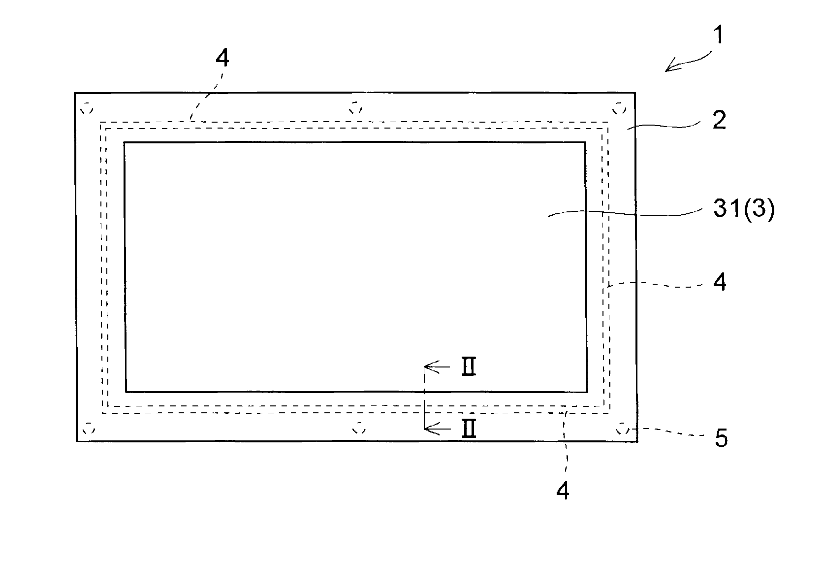
[0026]Hereinafter, embodiments of the present invention will be described with reference to the drawings. The same components will be identified by common reference signs, and detailed description of them will be omitted if possible. This embodiment relates to a cabinet structure for a display apparatus, the cabinet structure being provided with: a liquid crystal module provided with a liquid crystal panel; a front cabinet that is provided with an open window portion through which a display screen of the liquid crystal panel is exposed; and a rear cabinet that is joined to the front cabinet to form a cabinet main body in which the liquid crystal module is accommodated.

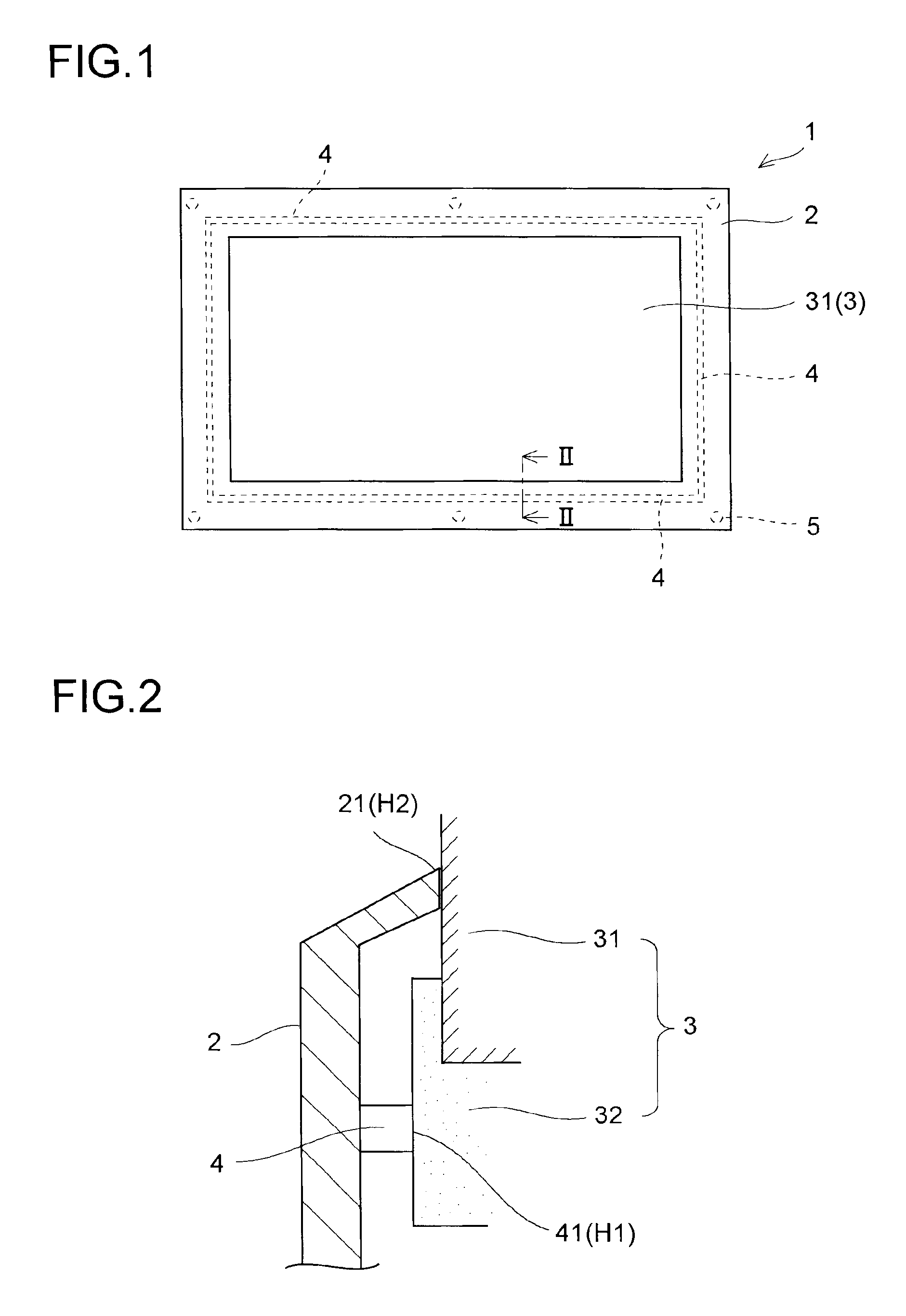
[0027]The display apparatus 1 of this embodiment is a display apparatus using a liquid crystal panel, and is provided with, as shown in FIG. 1, a front cabinet 2 and a liquid crystal module 3 that forms a display screen by exposing a liquid crystal panel 31 through an open window portion of the front cabinet 2. In addi...


PUM

PropertyMeasurementUnit
convex height H1aaaaaaaaaa
height H1aaaaaaaaaa
convex height H1aaaaaaaaaa

Abstract

The present invention relates to a cabinet structure for a display apparatus such as a liquid crystal television. The cabinet structure of a display apparatus 1 is provided with: a liquid crystal module 3 provided with a liquid crystal panel 31; a front cabinet 2 that has an open window portion through which a display screen of the liquid crystal panel is exposed; and a rear cabinet that is joined to the front cabinet to form a cabinet main body in which the liquid crystal module is accommodated, and the liquid crystal module 3 is fitted to the front cabinet 2, in a state in which a convex-curved press rib 4 that is curved along a length direction thereof to be convex is pressed against a bezel 32 of the liquid crystal module 3. Thus, a simpler cabinet structure for a display apparatus is achieved that is capable of realizing a preferable appearance of the display screen of the liquid crystal panel and the cabinet when they are assembled together, and that is capable of preventing the occurrence of vibration noise.

Description

[0001]This application is based on Japanese Patent Application No. 2009-025602 filed on Feb. 6, 2009, the contents of which are hereby incorporated by reference.BACKGROUND OF THE INVENTION[0002]1. Field of the Invention[0003]The present invention relates to a cabinet structure for a display apparatus such as a liquid crystal television.[0004]2. Description of Related Art[0005]A conventional cabinet structure for a display apparatus such as a liquid crystal television is such that a liquid crystal module provided with a liquid crystal panel is fitted in a box-shaped cabinet composed of a front cabinet and a rear cabinet. In the front cabinet, there is provided an open window portion through which a display screen of the liquid crystal panel is exposed.[0006]The liquid crystal module is built as a unit provided with components such as a liquid crystal panel, a drive circuit for driving the liquid crystal panel, a tuner for receiving a broadcast signal, and a circuit board having, for ...

Claims


Application Information

Patent Timeline
Patent Type & Authority Applications(United States)
IPC IPC(8): G02F1/1333
CPCH04N5/64
Inventor ISHII, HIROKI
Owner FUNAI ELECTRIC CO LTD
Why Eureka
Try Eureka