
Drainage structure in fuel cell motorcycle

a fuel cell motorcycle and drainage structure technology, applied in cycle equipment, sustainable manufacturing/processing, final product manufacturing, etc., can solve the problems of increased vehicle width, impaired vehicle appearance, and difficulty in flexible layout of drainage ports or foot steps for passengers or the like, so as to increase the width of the vehicle and reduce the appearance

Inactive Publication Date: 2012-02-21
HONDA MOTOR CO LTD
View PDF25 Cites 7 Cited by
  • Summary
  • Abstract
  • Description
  • Claims
  • Application Information

AI Technical Summary

Benefits of technology

The present invention provides a fuel cell motorcycle with a drainage structure that prevents water generated in the fuel cell from splashing onto the tires or legs of a passenger. The drainage pipe is connected to the fuel cell and extends rearwardly through the power unit. A drainage port is provided at the rear end of the drainage pipe, and a muffler is stored in the power unit to reduce exhaust noise. The layout of the drainage port prevents the possibility of water falling on the passenger's leg, and the arrangement of the drainage pipe in the power unit maximizes space usage and improves the appearance of the motorcycle.

Problems solved by technology

In order to avoid such an event, the flexible layout of the drainage port or a foot step for the passenger or the like becomes difficult.
When the drainage port is arranged on the side of the vehicle body, the width of the vehicle is increased, and the appearance of the vehicle body may be impaired by the drainage port exposed on the side of the vehicle.
Therefore, in the fuel cell motorcycle, the layout of the drainage port is a problem to solve.

Method used


Image

  • Drainage structure in fuel cell motorcycle
  • Drainage structure in fuel cell motorcycle
  • Drainage structure in fuel cell motorcycle

Examples


Embodiment Construction

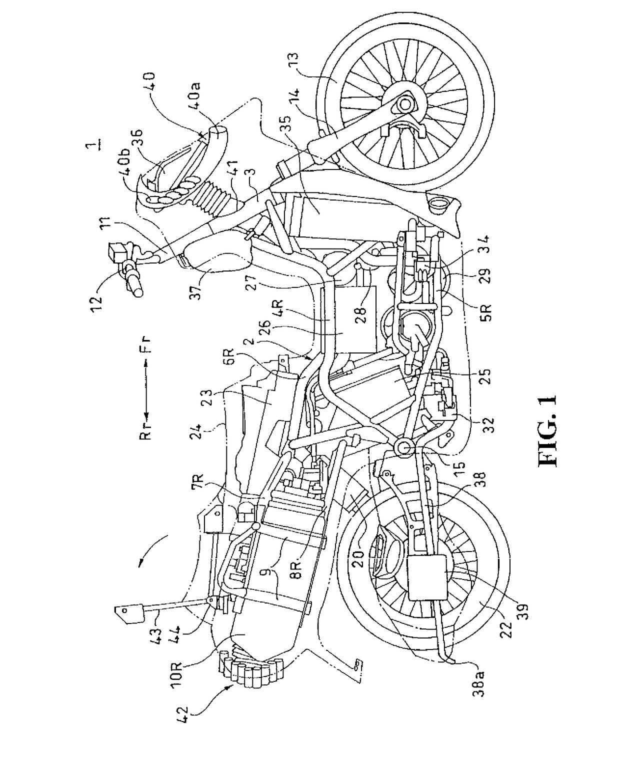
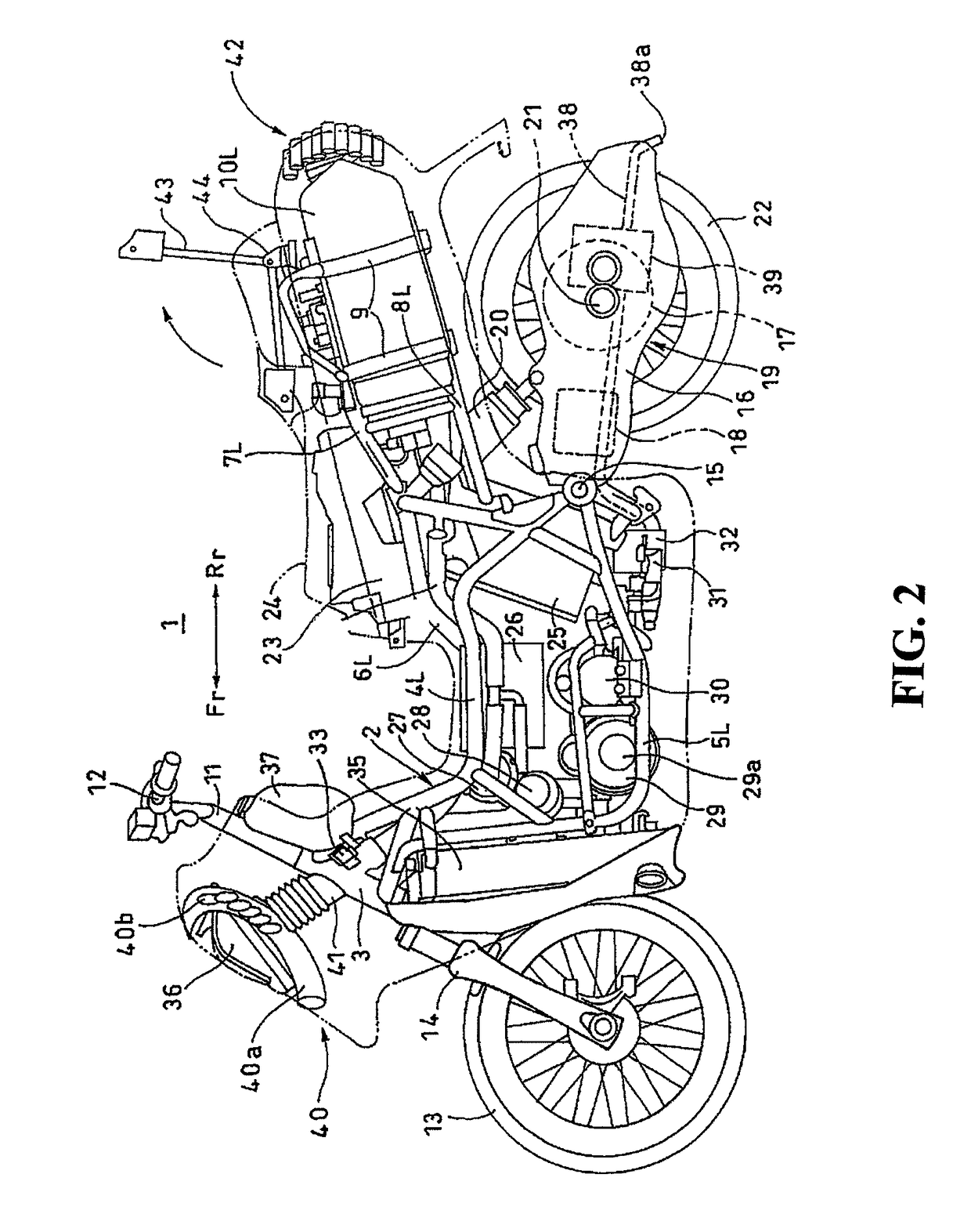
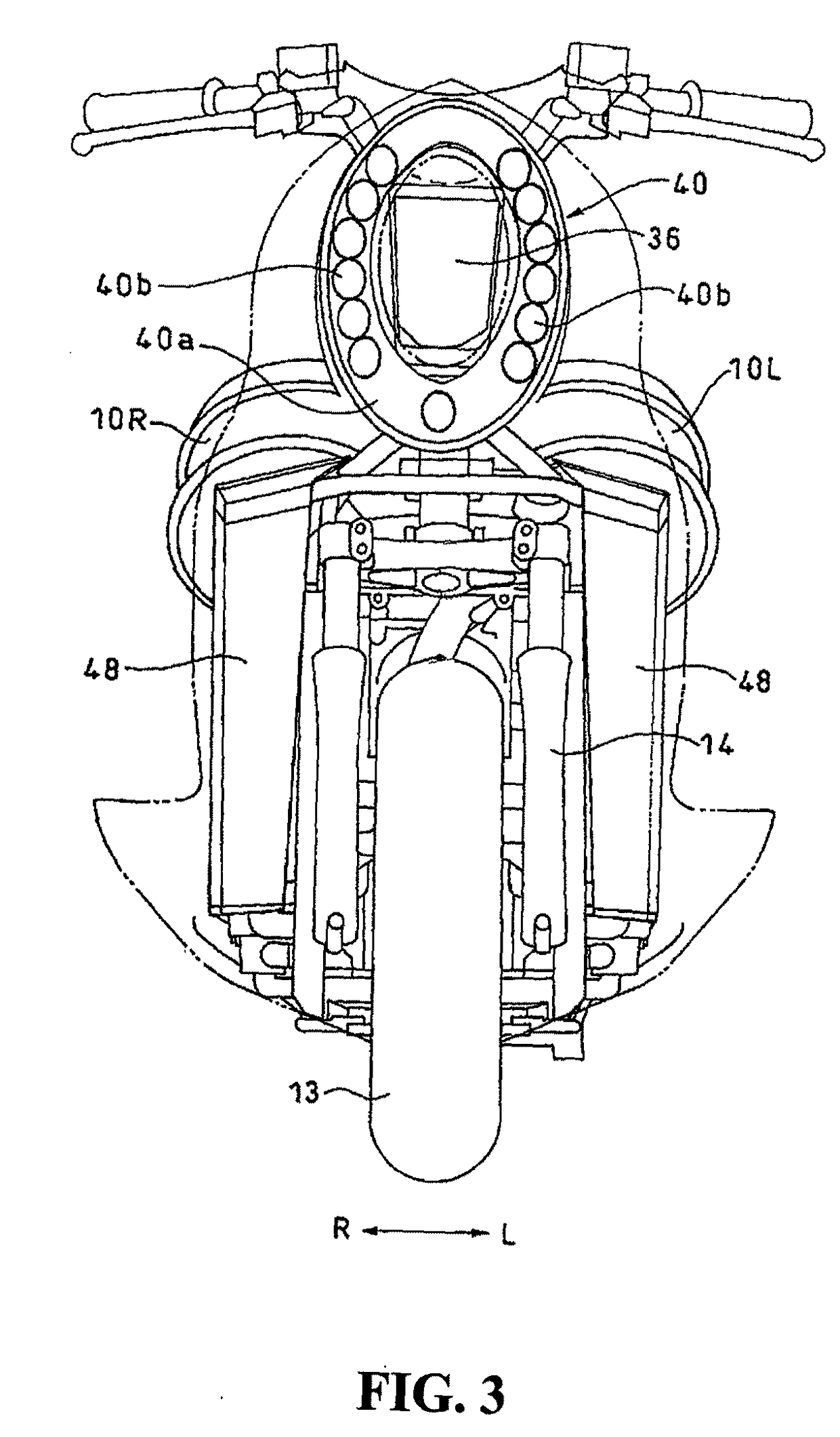
[0020]Referring now to the drawings, an embodiment of the present invention will be described. As illustrated in FIGS. 1 to 4, pairs of left and right parts of a fuel cell motorcycle 1 are distinguished by the designation “L” for those on the left side and the designation “R” for those on the right side. The fuel cell motorcycle has a fuel generator system including a hydrogen supply system, an oxygen supply system and a cell stack (including electrodes, separator, and electrolyte) for generating electric energy through an electrochemical reaction. The cell stack and a casing for storing the same (including members associated with the casing) in combination are referred to as a fuel cell.

[0021]A frame body 2 of the fuel cell motorcycle (hereinafter, referred simply to as “motorcycle”) 1 includes a head pipe 3, upper frames 4L, 4R and lower frames 5L, 5R being joined at the front ends thereof to the head pipe 3 and extending rearwardly (the direction indicated by a reference sign Rr)...


PUM

PropertyMeasurementUnit
electric poweraaaaaaaaaa
flexibleaaaaaaaaaa
electric energyaaaaaaaaaa

Abstract

A layout for an exhaust pipe which also serves as a drainage pipe which prevents splashing of water generated in a fuel cell toward a passenger or splashing toward a tire. Humid excessive gas supplied from a fuel cell is diluted in a dilution box by off-gas discharged from the fuel cell and is used for humidifying air in the humidifier. An exhaust pipe is connected to the dilution box, and diluted hydrogen gas is discharged via the exhaust pipe. Vapor mixed in hydrogen gas is condensed in the exhaust pipe and turned into water, which is drained through the exhaust pipe that extends rearwardly of a vehicle body through the interior of a power unit. A discharge port of the exhaust pipe (which is also a drainage port for water generated in the fuel cell) is positioned at the widthwise center of the vehicle body.

Description

CROSS-REFERENCE TO RELATED APPLICATIONS[0001]The present application claims priority under 35 USC 119 to Japanese Patent Application No. 2007-056273 filed on Mar. 6, 2007 the entire contents of which are hereby incorporated by reference.BACKGROUND OF THE INVENTION[0002]1. Field of the Invention[0003]The present invention relates to a fuel cell motorcycle and, more specifically, to a fuel cell motorcycle having a drainage system for draining water generated in a fuel cell out of a vehicle body.[0004]2. Description of Background Art[0005]A fuel cell is now considered as a way to provide a propulsion for a vehicle while protecting the environment and reserving energy resources as compared to conventional vehicles that require fossil fuel. A fuel cell motorcycle using a motor driven by electric energy generated by the fuel cell as a power source is being developed. When the fuel cell generates electric power, hydrogen ion and electrons are emitted from hydrogen as fuel. The hydrogen ion...

Claims


Application Information

Patent Timeline
Patent Type & Authority Patents(United States)
IPC IPC(8): B60K1/04B62D61/02B60K13/06B60K13/04B62J99/00B60K8/00B60L11/18B62M7/02H01M8/00H01M8/10
CPCB60K1/04B62K11/04B62K11/10B62M23/02H01M8/04291B60Y2200/12B62K2202/00B62K2204/00H01M8/04044H01M2250/20Y02T90/32Y02E60/50Y02T90/40Y02P70/50
Inventor ITO, MASAMOTOKIKUCHI, HIROYUKI
Owner HONDA MOTOR CO LTD
Learn More