Video signal coding apparatus and video signal coding method

a video signal and coding apparatus technology, applied in signal generators with optical-mechanical scanning, color televisions with bandwidth reduction, signal systems, etc., can solve the problem that the rate control operation cannot achieve the desired operation, and achieve excellent image quality and strain on luminance code amount.

Active Publication Date: 2010-08-12
PANASONIC CORP
View PDF4 Cites 37 Cited by
  • Summary
  • Abstract
  • Description
  • Claims
  • Application Information

AI Technical Summary

Benefits of technology

[0046]Specifically, it is possible to perform control so as to keep the rate between the luminance code amount and the chrominance code amount within a fixed range. This prevents the occurrence of a situation in which, for example...

Problems solved by technology

However, as described above, the quantization step for the code amount of the chrominance signal is only doubled, and thus the code amount of the chrominance signal after codi...

Method used


Image

  • Video signal coding apparatus and video signal coding method
  • Video signal coding apparatus and video signal coding method
  • Video signal coding apparatus and video signal coding method

Examples


Embodiment Construction

)

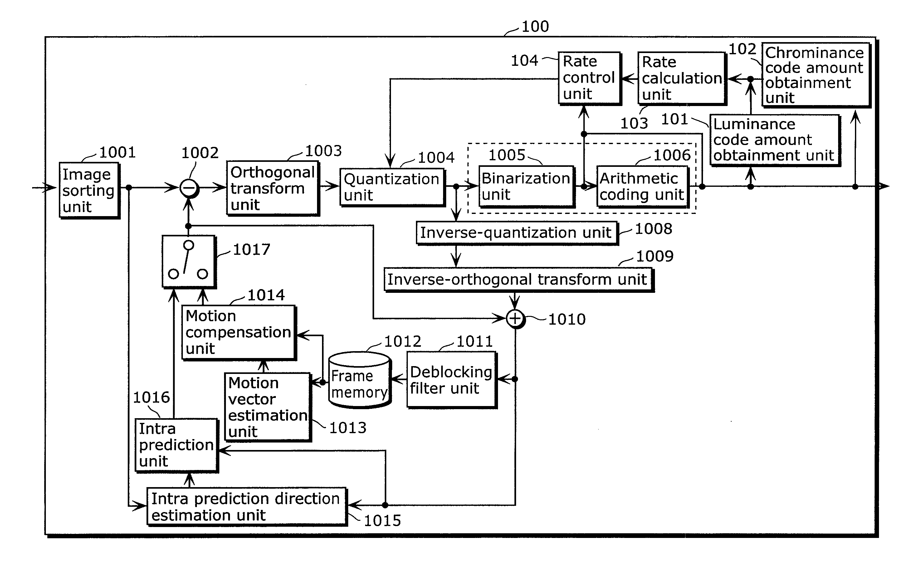
[0059]A video signal coding apparatus according to an implementation of the present invention is a video signal coding apparatus which performs coding involving quantization on a video signal including a luminance signal and a chrominance signal, and outputs a coded signal including a coded luminance signal and a coded chrominance signal, the video signal being a signal of a video, the video signal coding apparatus including: a quantization unit configured to quantize a luminance signal of each of a first picture and a second picture using coefficient values indicated in a first quantization matrix, and to quantize a chrominance signal of each of the first picture and the second picture using coefficient values indicated in a second quantization matrix, the first picture and the second picture being included in the video, and the second picture being coded subsequent to the first picture; a code amount obtainment unit configured to obtain a luminance code amount and a chrominance c...


PUM


Abstract

Video signal coding apparatus includes: a quantization unit which quantizes, using coefficient values in a first quantization matrix, a luminance signal of each of a first picture and a second picture coded after the first picture, and quantizes, using coefficient values in a second quantization matrix, a chrominance signal of each of the first picture and the second picture; a code amount obtainment unit which obtains a luminance code amount and a chrominance code amount of each of the first picture and the second picture; a rate calculation unit which calculates a rate of the chrominance code amount with respect to the luminance code amount for each of the first picture and the second picture, obtained by the code amount obtainment unit; and a rate control unit which changes a coefficient value of at least one of the first matrix and the second matrix used in quantizing the second picture, before the quantization unit quantizes the second picture, so that the rate for the second picture becomes smaller than the rate for the first picture.

Description

BACKGROUND OF THE INVENTION[0001](1) Field of the Invention[0002]The present invention relates to a video signal coding apparatus and video signal coding method for coding a video signal, and particularly relates to a rate controlling technique.[0003](2) Description of the Related Art[0004]In recent years, digitalization of AV information is advancing, and devices that can handle video signals by digitalization are becoming widely popular. Since the amount of information included in a video signal is large, it is a common practice to perform coding while reducing the amount of information, in consideration of recording capacity and transmission efficiency. An international standard developed by a working group called the Moving Picture Experts Group (MPEG) is widely used as a technique for coding video signals.[0005]Here, H.264 (for example, see Non-Patent Reference 1: ITUT-T H.264 (03 / 2005): Infrastructure of audiovisual services—Coding of moving video, Advanced video coding for ge...

Claims


Application Information

Patent Timeline
IPC IPC(8): H04N7/26H04N19/00H04N19/126H04N19/136H04N19/146H04N19/189H04N19/196H04N19/423H04N19/503H04N19/51H04N19/513H04N19/593H04N19/80H04N19/85H04N19/91
CPCH04N19/172H04N19/15H04N19/186H04N19/126H04N19/61
Inventor ARAKAWA, HIROSHIMARUYAMA, YUKIOHGOSE, HIDEYUKIABE, KIYOFUMI
Owner PANASONIC CORP
Why Eureka
Try Eureka