Retinal prosthesis

a prosthesis and retinal technology, applied in the field of implantable medical devices, can solve problems such as difficulty in implanting in the available sub-retinal or epi-retinal spa

Active Publication Date: 2010-08-12
NANO RETINA INC
View PDF88 Cites 62 Cited by
  • Summary
  • Abstract
  • Description
  • Claims
  • Application Information

AI Technical Summary

Benefits of technology

[0083]In an embodiment, the intraocular device includes a plurality of microlenses coupled to the energy receiver, facilitating refraction of visible light toward the photosensors.

Problems solved by technology

In particular, given the very small volume available in the sub-retinal or the epi-retinal space, the inventors have determined that receiving energy by radiofrequency (RF) or wired electricity transmission requires a coil or a battery that are particularly large, and difficult to implant in the available sub-retinal or epi-retinal space.

Method used


Image

  • Retinal prosthesis
  • Retinal prosthesis
  • Retinal prosthesis

Examples


Embodiment Construction

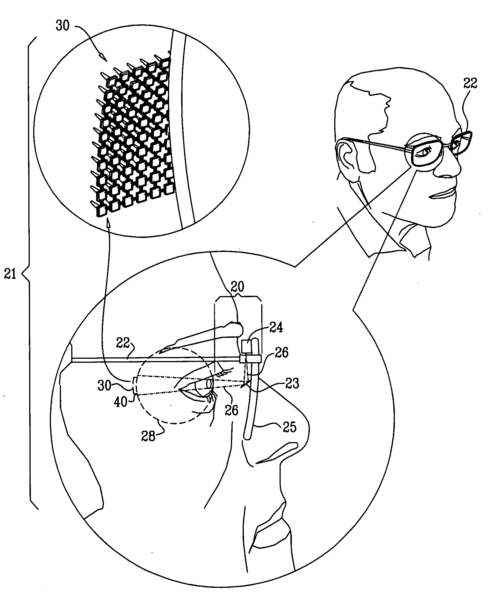
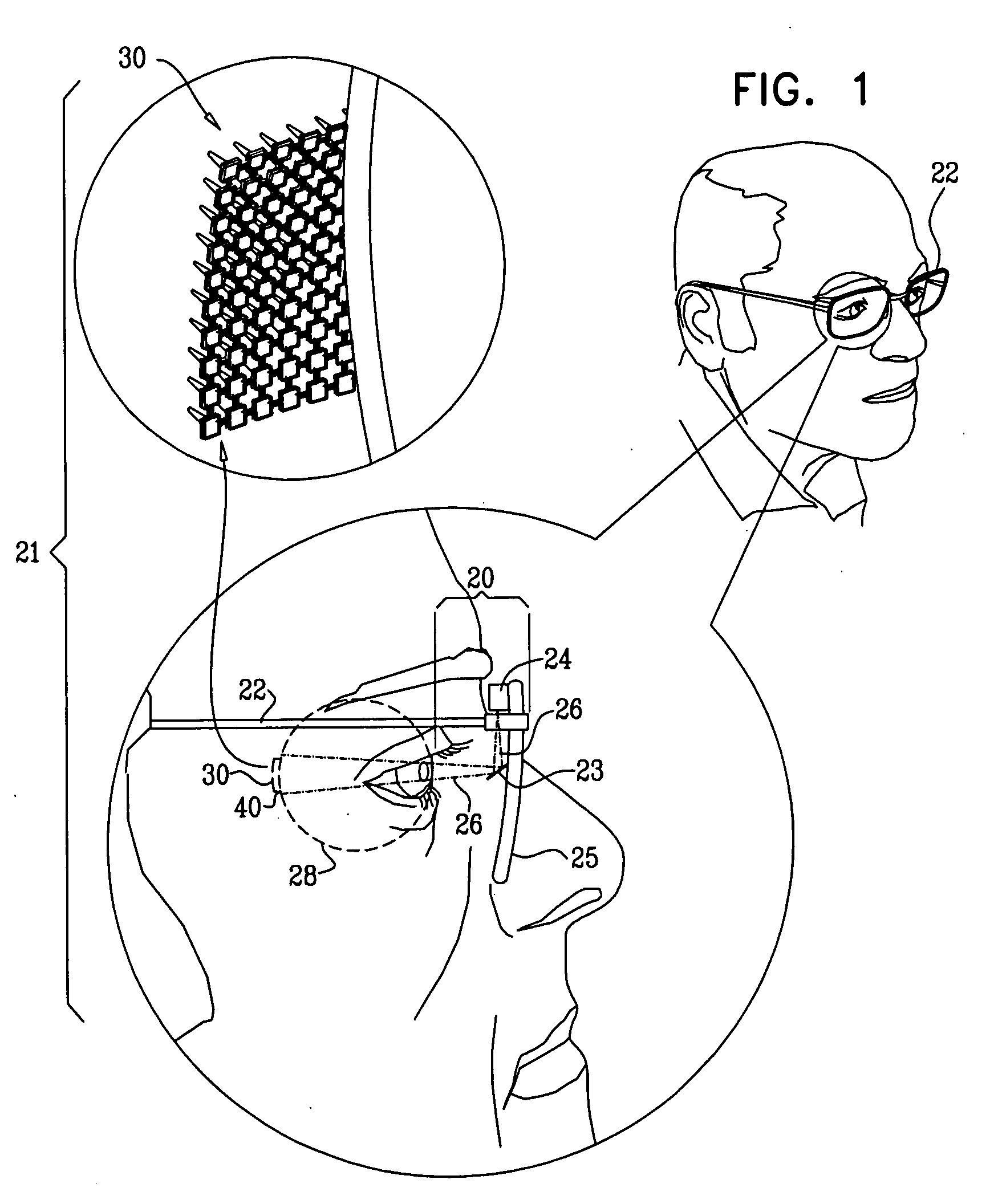
[0104]FIG. 1 is a schematic illustration of apparatus 21 for restoring at least partial vision in a subject suffering from retinal malfunction, in accordance with an embodiment of the present invention. Apparatus 21 comprises an external device 20 comprising a mount 22, which is typically a pair of eyeglasses, and is placed in front of a subject's eye 28. External device 20 further comprises a power source, for example a laser 24, which is coupled to the mount and is configured to emit radiated energy 26 that is outside the visible range toward the subject's eye 28. Laser 24 is shown coupled to the inner part of lens 25 by way of illustration and not limitation. Laser 24 may be coupled to other members of mount 22 for example, to the arm of the eyeglasses.

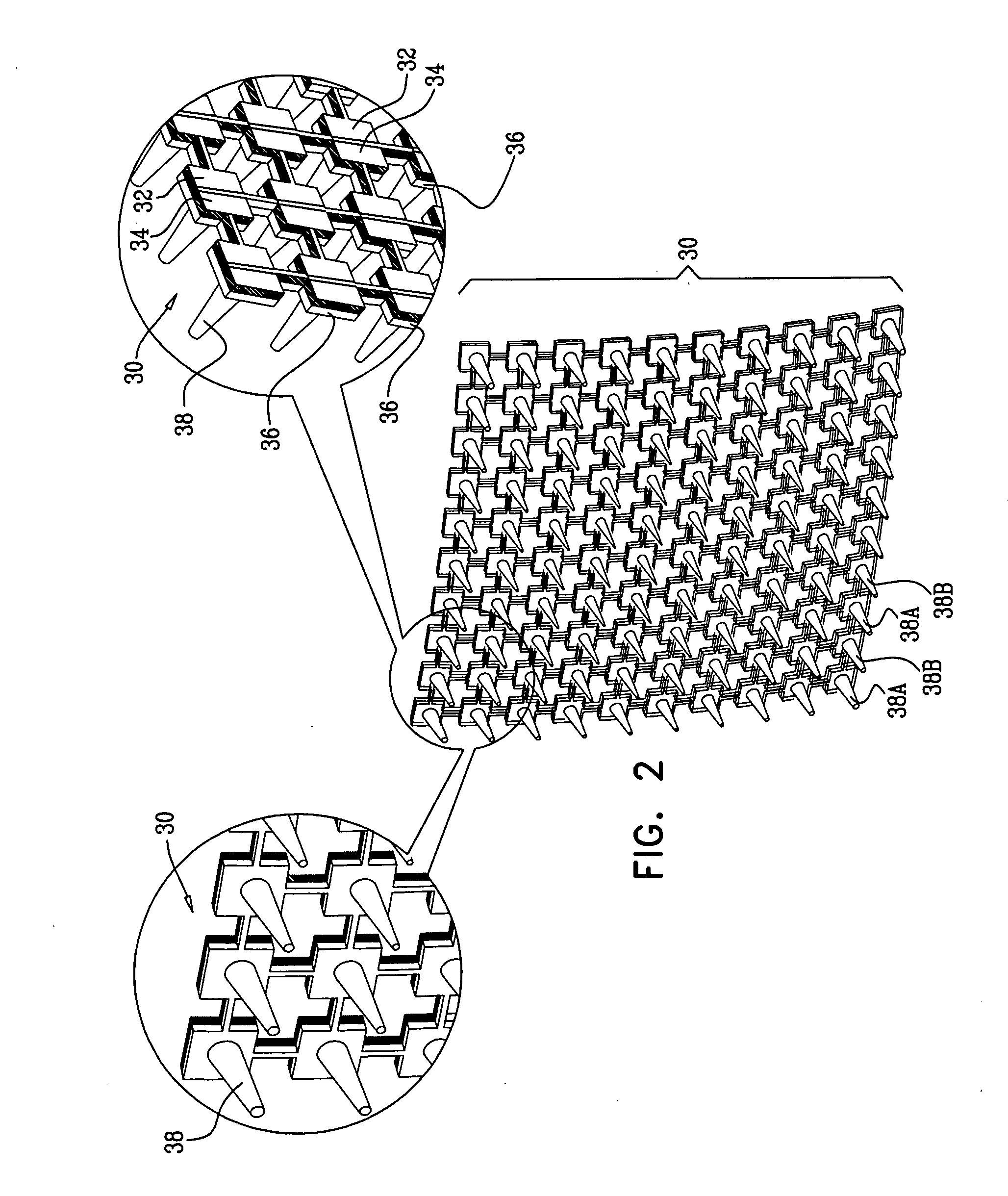
[0105]Apparatus 21 additionally comprises an intraocular device 30, which is implanted entirely in eye 28. Intraocular device 30 comprises a small e.g., 3-6 mm in diameter, thin e.g., less than 1 mm thick, and typically flexible si...


PUM


Abstract

Apparatus is provided, including an external device, including a mount, which is placed in front of an eye of a subject. A laser is coupled to the mount and configured to emit toward the eye radiation that is outside of 380-750 nm. A partially-transparent mirror is coupled to the mount. An intraocular device is implanted entirely in the subject's eye, and includes a plurality of stimulating electrodes, and an energy receiver, which receives the radiation from the laser and generates a voltage drop in response thereto. A plurality of photosensors detect photons and generate a signal in response thereto. Driving circuitry is coupled to the energy receiver and to the photosensors, and receives the signals from the photosensors and utilizes the voltage drop to drive the electrodes to apply currents to the retina in response to the signals from the photosensors. Other embodiments are also described.

Description

FIELD OF THE INVENTION[0001]The present invention relates generally to implantable medical devices, and specifically to a retinal prosthesis.BACKGROUND OF THE INVENTION[0002]Retinal malfunction, due to degenerative retinal diseases, is a leading cause of blindness and visual impairment. Implantation of a retinal prosthesis is a technology for restoring some useful vision in individuals suffering from retinal-related blindness.[0003]The retina is a multi-layered light-sensitive structure that lines the posterior, inner part of the eye. The retina contains photoreceptor cells, for example rods and cones, which capture light and convert light signals into neural signals transmitted through the optic nerve to the brain. Rods are responsible for light sensitive, low resolution black and white vision, whereas cones are responsible for high resolution color vision. Most cones lie in the fovea, which defines the center of the retina.[0004]U.S. Pat. No. 6,976,998 to Rizzo et al. describes an...

Claims


Application Information

Patent Timeline
Patent Type & Authority Applications(United States)
IPC IPC(8): A61N1/36
CPCA61N1/0543A61N1/36046A61N1/37217H01L31/145H01L27/14621H01L27/14627A61N1/3787
Inventor GROSS, YOSSIVAINGAST, SHAI
Owner NANO RETINA INC
Why Eureka
Try Eureka