
Pressure Controller for Artificial Respirator and Artificial Respirator Using the Same

a technology of pressure controller and artificial respirator, which is applied in the direction of breathing mask, breathing protection, life-saving devices, etc., can solve the problem of not operating of the adjustment operating member, and achieve the effect of effective correcting the drawbacks of the pressure controller and simple arrangemen

Active Publication Date: 2010-08-19
ATOM MEDICAL
View PDF1 Cites 34 Cited by
  • Summary
  • Abstract
  • Description
  • Claims
  • Application Information

AI Technical Summary

Benefits of technology

[0009]The present invention can effectively correct the drawbacks of the pressure controller of patent reference as described above with a relatively simple arrangement.
[0010]According to the first aspect of the present invention, the present invention is a pressure controller for use in an artificial respirator such as a resuscitator for supplying a gas to a patient requiring respiration assistance, comprising a housing mechanism which has a first vent hole, a second vent hole and a third vent hole, and in which one of the first vent hole and the second vent hole is configured to be used as an inlet of an inspiratory gas and the other vent hole is configured to be used as an outlet of the inspiratory gas, a control valve placed in the housing mechanism to face a gas passage between the first vent hole and the second vent hole, elastic biasing means for elastically biasing the control valve against a valve seat formed in the housing mechanism, an adjustment operating member to be operated to adjust an elastic biasing force of the elastic biasing means, and an adjustment manipulating member to be pivoted to operate the adjustment operating member, wherein the control valve closes the third vent hole when a gas pressure in the gas passage is lower than a predetermined level, and the control valve opens the third vent hole such that a gas in the gas passage flows through the third vent hole when the gas pressure in the gas passage is higher than a predetermined level, characterized in that the adjustment operating member does not operate even when the adjustment manipulating member pivots by a pivoting operation of the adjustment manipulating member in a first state in which the adjustment manipulating member moves backward to the adjustment operating member, and the adjustment operating member operates to adjust the elastic biasing force of the elastic biasing means when the adjustment manipulating member pivots by the pivoting operation of the adjustment manipulating member in a second state in which the adjustment manipulating member is pulled out from the adjustment operating member. In this configuration of the first aspect (the second aspect to be described later is the same}, the adjustment manipulating member need not be covered with any pivotal motion preventing locking cap in order to prevent an unnecessary pivotal motion of the adjustment manipulating member. This simplifies the pivoting operation of the adjustment manipulating member as a whole. Also, there is no problem in reliably preventing unnecessary operating of the adjustment operating member. Furthermore, when the adjustment manipulating member moves backward to the adjustment operating member, the adjustment operating member does not operate even if the adjustment manipulating member pivots by the pivoting operation of the adjustment manipulating member. Accordingly, the adjustment manipulating member is not pivoted by a very large force unlike when the pivotal motion of the adjustment manipulating member is forcedly inhibited. This protects the adjustment manipulating member, adjustment operating member and the like from being broken.

Problems solved by technology

Furthermore, when the adjustment manipulating member moves backward to the adjustment operating member, the adjustment operating member does not operate even if the adjustment manipulating member pivots by the pivoting operation of the adjustment manipulating member.

Method used


Image

  • Pressure Controller for Artificial Respirator and Artificial Respirator Using the Same
  • Pressure Controller for Artificial Respirator and Artificial Respirator Using the Same
  • Pressure Controller for Artificial Respirator and Artificial Respirator Using the Same

Examples


Embodiment Construction

[0040]An embodiment in which the present invention is applied to a pressure controller of a T-piece resuscitator will be explained below with reference to the accompanying drawings in the order of “1. Outline of Arrangement of Overall T-Piece Resuscitator”, “2. Arrangement of Pressure Controller”, “3. Procedures of Assembling Pressure Controller”, “4. Operation of Pressure Controller”, and “5. Method of Using T-Piece Resuscitator”.

[0041]1. Outline of Arrangement of Overall T-Piece Resuscitator as Shown in FIG. 8, a T-Piece Resuscitator Includes:

[0042](a) a resuscitator main body 1,

[0043](b) a gas source (not shown) that supplies an inspiratory gas to the resuscitator main body 1 through a gas supply tube 2,

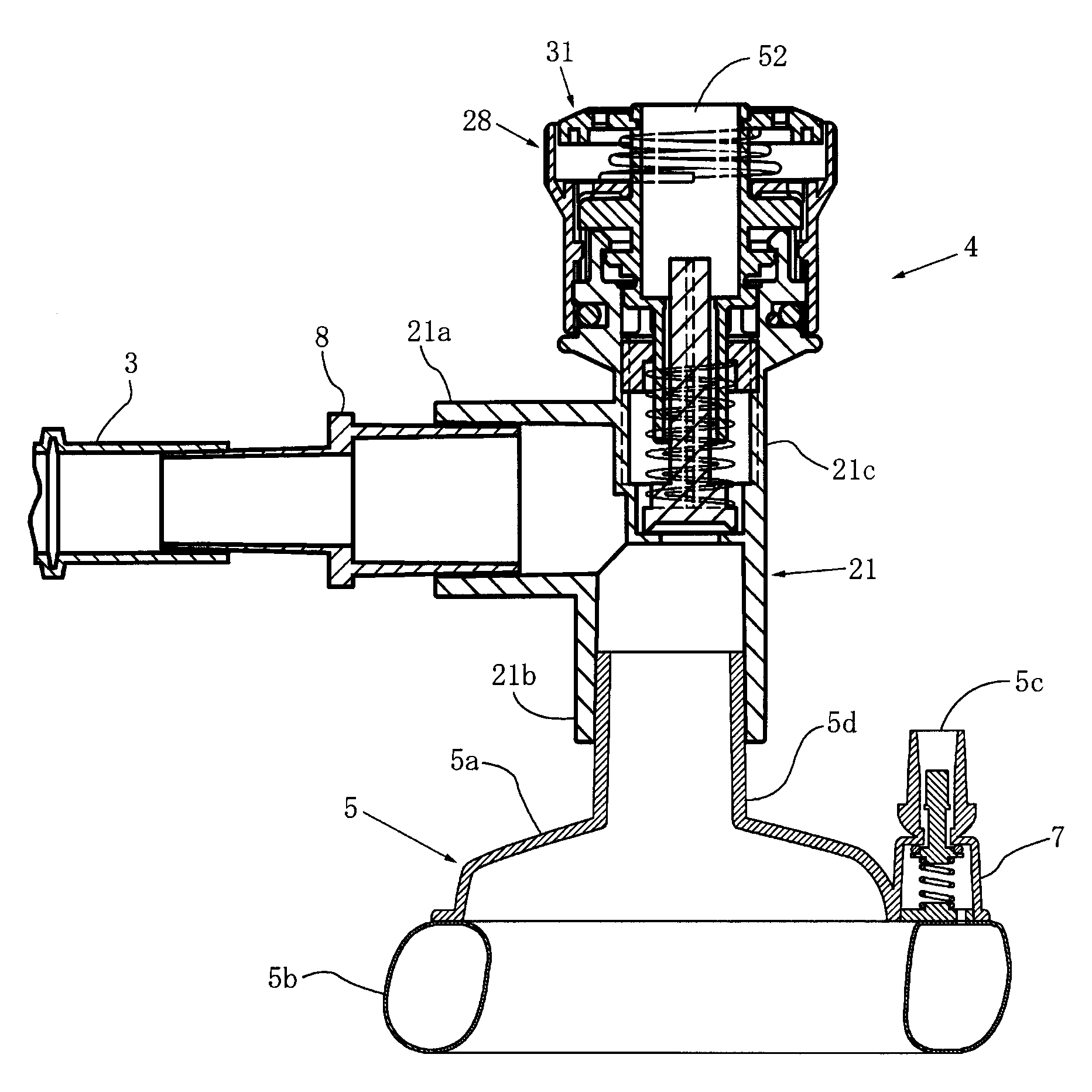
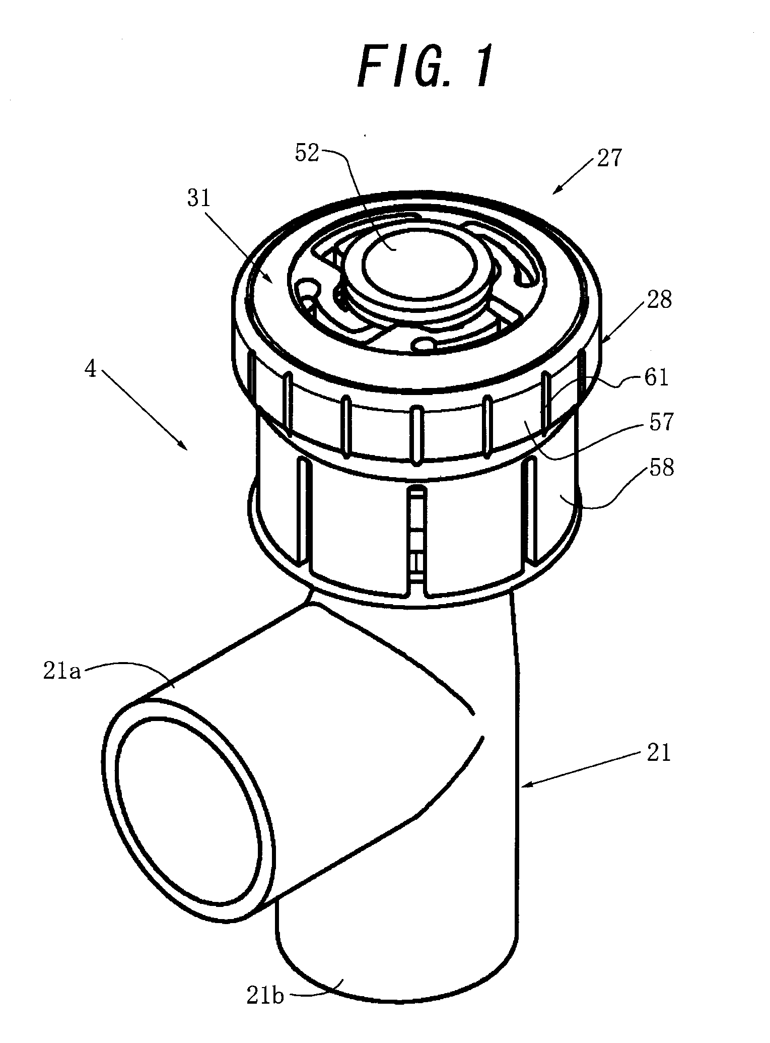
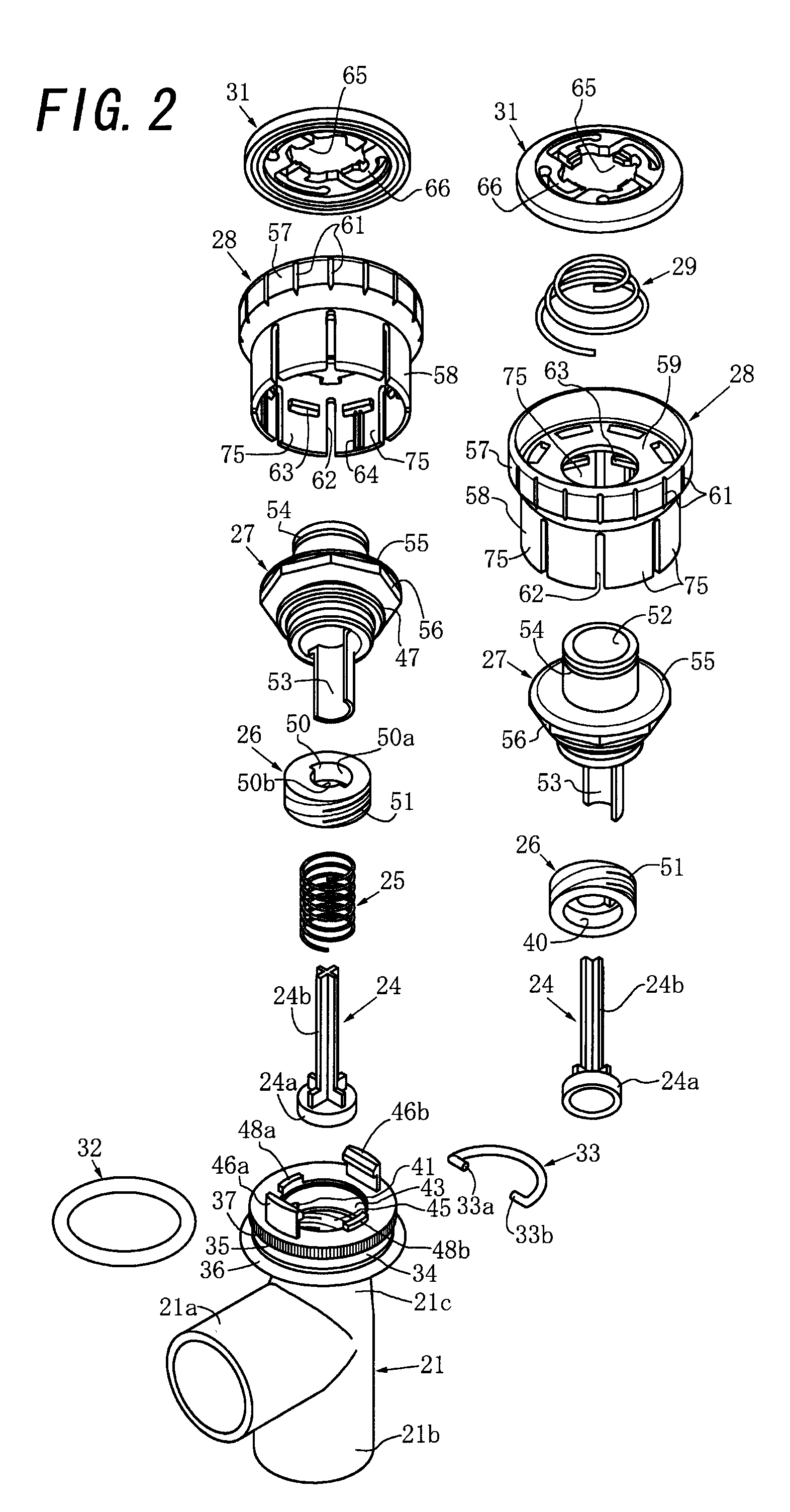
[0044](c) a pressure controller 4 to which the resuscitator main body 1 supplies the inspiratory gas through a gas supply tube 3, and

[0045](d) a face mask 5 attached to the pressure controller 4.

[0046]The pressure controller 4 is also called a patient T-piece. A ring-like air bag ...


PUM


Abstract

A pressure controller for an artificial respirator according to this invention includes a control valve facing a gas passage between an inspiratory gas inlet and an inspiratory gas outlet, and an elastic biasing means for elastically biasing the control valve against a valve seat. When an adjustment manipulating member moves backward, even the pivotal motion of the adjustment manipulating member does not operate an adjustment operating member. When the adjustment manipulating member is pulled out, the pivotal motion of the adjustment manipulating member operates the adjustment operating member, thereby adjusting the elastic biasing force of the elastic biasing means. This invention provides a pressure controller for an artificial respirator capable of reliably preventing unnecessary operating of the adjustment operating member although the pivoting operation of the adjustment manipulating member is simple as a whole, and there is no possibility that the adjustment manipulating member and the like are broken.

Description

CROSS-REFERENCE TO RELATED APPLICATIONS [0001]This application claims benefit of the Japanese Patent Application No. 2009-32371, entitled “Pressure Controller for Artificial Respirator and Artificial Respirator Using the Same,” filed on Feb. 16, 2009, the entire content of which is hereby incorporated by reference.TECHNICAL FIELD [0002]The present invention relates to a pressure controller for use in an artificial respirator such as a resuscitator for supplying a gas to a patient requiring respiratory assistance, comprising a housing mechanism which has a first vent hole, a second vent hole and a third vent hole, and in which one of the first vent hole and the second vent hole is configured to be used as an inlet of an inspiratory gas and the other vent hole is configured to be used as an outlet of the inspiratory gas, a control valve placed in the housing mechanism to face a gas passage between the first vent hole and the second vent hole, elastic biasing means for elastically bias...

Claims


Application Information

Patent Timeline
IPC IPC(8): A61M16/20A61M16/00
CPCA61M16/0816A61M16/209A61M16/208A61M16/0833
Inventor MATSUBARA, TERUMIOTOMO, TOSHIOSEKIGUCHI, YUTAKATANABE, TAKASHIMATSUBARA, KAZUO
Owner ATOM MEDICAL
Learn More