Hair Iron

a technology of hair iron and hair shaft, which is applied in the field of hair iron, can solve problems such as the damage of hair finishing, and achieve the effect of maintaining healthy hair

Inactive Publication Date: 2010-08-19
MUKAI TAKASHI
View PDF7 Cites 9 Cited by
  • Summary
  • Abstract
  • Description
  • Claims
  • Application Information

AI Technical Summary

Benefits of technology

[0012]Accordingly, the second correcting surface can regulate and gloss the surface of hair and the first correcting surface can increase contact points or contact areas that are in contact with the hair during treatment. This results in dispersing force acting on the cross section of each hair and maintaining the hair healthy after the treatment.

Problems solved by technology

A problem to be solved is that treating the surface of each hair with the surfaces of the correctors results in concentrating heat and force on cross-sectional two side points of the hair that are in contact with the correctors and finishing the hair in a damaged state.

Method used


Image

  • Hair Iron
  • Hair Iron
  • Hair Iron

Examples


Embodiment Construction

[0026]Objects of regulating the surface of hair with the surfaces of correctors and dispersing force acting on cross sectional points of each hair that are in contact with the correctors are realized by making one of the correcting surfaces rougher than the other, to thereby increase contact points or contact areas that are in contact with the hair.

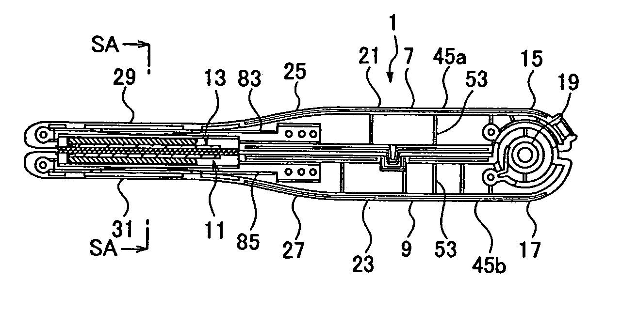
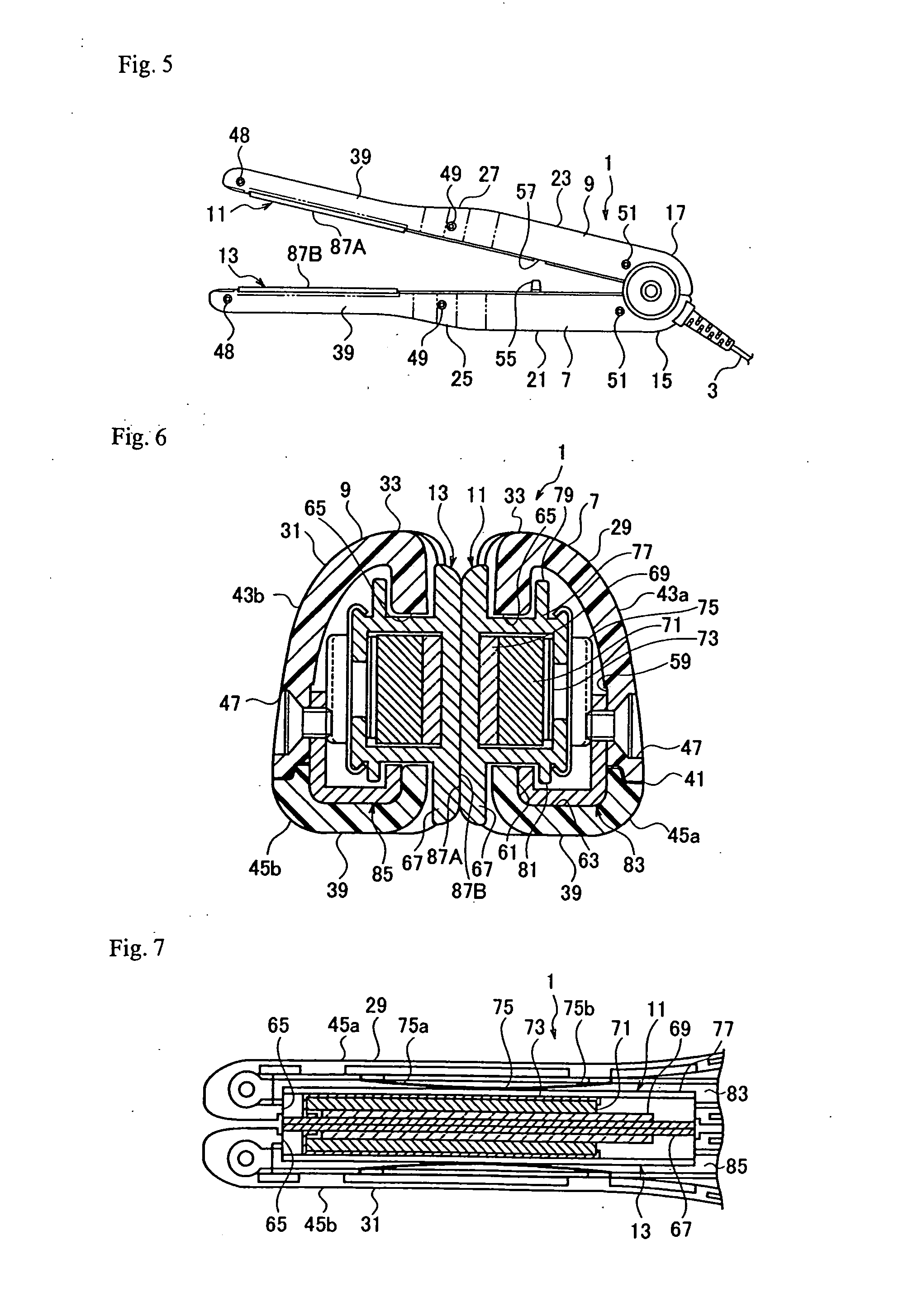
[0027]FIGS. 1 to 5 show a hair iron according to an embodiment of the present invention, in which FIG. 1 is a general perspective view partly omitted, FIG. 2 a plan view partly broken with divisional parts removed, FIG. 3 a side view, FIG. 4 a plan view, and FIG. 5 a bottom view with clamp arms opened.

[0028]As shown in FIGS. 1 to 5, the hair iron 1 has an iron body 5 to which a power source cord 3 is connected. The power source cord 3 is provided with a power source plug and the like.

[0029]The iron body 5 has a pair of clamp arms 7 and 9 and a pair of correctors 11 and 13. The clamp arms 7 and 9 are made of resin such as C-polyester-based...


PUM


Abstract

A hair iron can regulate the surface of hair with the surfaces of correctors and disperse force acting on cross sectional points of each hair that are in contact with the correctors. The hair iron has clamp arms and the correctors that are arranged on the clamp arms, to face each other, hold hair between them, and heat the hair. At this time, correcting surfaces hold and correct the hair. The correcting surface of one of the correctors is roughened with irregularities to increase contact points or contact areas with the hair and the correcting surface of the other corrector is formed to be smoother than the correcting surface.

Description

BACKGROUND OF THE INVENTION[0001]The present invention relates to a hair iron used to straighten curly hair and the like.[0002]A conventional hair iron is, for example, the one shown in FIG. 13 (refer to Patent Literature 1). FIG. 13(a) is a general schematic view showing the hair iron and FIG. 13(b) is a sectional view showing the inside thereof.[0003]As shown in FIG. 13, the conventional hair iron 201 has an iron body 203 to which a power source cord 205 is connected. An intermediate part of this power source cord 205 is connected to a temperature controller 207 and an end thereof is fitted to a power source plug 209.[0004]The iron body 203 has a pair of clamp arms 211 and 213 made of resin. The clamp arms 211 and 213 have base ends 215 and 217 that are joined to be rotatable relative to each other and front ends 219 and 221 where correctors 223 and 225 are arranged to face each other. The correctors 223 and 225 are movably supported by the clamp arms 211 and 213 so that the corre...

Claims


Application Information

Patent Timeline
Patent Type & Authority Applications(United States)
IPC IPC(8): A45D2/00
CPCA45D1/04A45D2200/202A45D2001/004A45D1/12A45D1/08
Inventor MUKAI, TAKASHI
Owner MUKAI TAKASHI
Why Eureka
Try Eureka