Ultra-high voltage transmission line clamp replacing tool

A technology of ultra-high voltage and transmission lines, which is applied in the direction of overhead lines/cable equipment, etc., and can solve problems such as wire falling off, failure to consider the stress situation, and damage to sub-wires, etc.

Active Publication Date: 2020-10-20
STATE GRID CORP OF CHINA +1
View PDF15 Cites 2 Cited by
  • Summary
  • Abstract
  • Description
  • Claims
  • Application Information

AI Technical Summary

Problems solved by technology

Usually, to deal with such defects, it is necessary to adopt the combined operation method of "suspension device + multi-split wire lifting hook". The decisive factor, if a problem occurs, it will lead to the serious consequences of the discharge of the wire to the tower or the loss of the wire
[0005] In the prior art, there have been clamp replacement tools fixed on the connecting plate, such as related tools with publication numbers CN208299324U and CN107706822A, but when the existing tools replace the clamps, the weight of the lifted sub-conductor is transmitted to the On other sub-conductors, but especially for even-numbered sub-conductors, such as 4-split conductors, the sub-conductor with the largest load is the one on the same side as the lifted sub-conductor, and the existing large number of connecting boards are not designed. Considering the relevant stress conditions, the area of ​​action between it and the sub-conductor is limited, which will cause the force on the corresponding load-bearing sub-conductor to be too concentrated, which may damage the sub-conductor and reduce the life of the sub-conductor.

Method used


Image

  • Ultra-high voltage transmission line clamp replacing tool
  • Ultra-high voltage transmission line clamp replacing tool

Examples


Embodiment Construction

[0033] First of all, it should be noted that the discussion of any embodiment of the present invention is only exemplary, and is not intended to imply that the scope of the present disclosure (including the claims) is limited to these examples; there are many other aspects of the present invention as described above. The changes, for brevity, they are not provided in the details. Therefore, other embodiments are also within the protection scope of the corresponding claims.

[0034] In addition, the drawings in the following description are only preferred embodiments of the present invention. For those of ordinary skill in the art, other drawings can be obtained based on these drawings without creative work. In addition, these embodiments are not used to limit the present invention. Any modification, equivalent replacement, improvement, etc., made within the spirit and principle of the present invention should be included in the protection scope of the present invention.

[0035] I...


PUM


Abstract

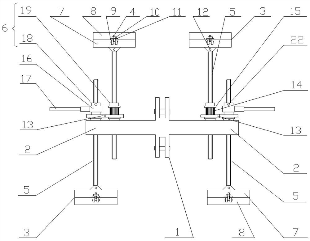
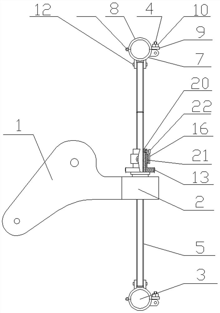
The invention provides an ultra-high voltage transmission line clamp replacing tool. The tool comprises a connecting plate used for being fixedly connected with a yoke plate, cross beams extending outof the left side and the right side of the connecting plate are arranged on the connecting plate. The connecting plate and the cross beam are in a vertical position relationship. The tail ends of thecross beams on the left side and the right side of the connecting plate are rotationally connected with two rotating nuts respectively. The rotating nuts are in threaded connection with lead screws,the lead screws are parallel to the connecting plate, sleeves are arranged at one ends of the lead screws, for the two lead screws located on the same side of the connecting plate, the ends, providedwith the sleeves, of the two lead screws are opposite in the vertical direction, and the directions of all the sleeves are approximately perpendicular to the connecting plate. The device can improve the stress of the branch wire in the operation of replacing the wire clamp, and protects the branch wire from being damaged.

Description

Technical field [0001] The invention relates to the technical field of tools for power transmission equipment, in particular to a tool for replacing ultra-high voltage transmission line clamps. Background technique [0002] The ultra-high voltage transmission line is an important part of the modern power grid system, and it is an inevitable requirement for the growth of power generation capacity and power load, and the extension of power transmission distance. Ultra-high voltage transmission is one of the important signs of the development level of the power industry. With the widespread development of electric energy utilization, many countries are building large-capacity hydropower stations, thermal power plants, nuclear power plants, and power stations, and power resources are often far away from load centers. Only by using ultra-high voltage transmission can the transmission task be achieved effectively and economically. Ultra-high voltage transmission can increase transmiss...

Claims


Application Information

Patent Timeline
Patent Type & Authority Applications(China)
IPC IPC(8): H02G1/02
CPCH02G1/02
Inventor 赵志刚王军康淑丰梁利辉张明旭李俭苏永杰马昊李吉林许文广孙二辉刘洪吉吴二波池城刘海峰杨阳赵军
Owner STATE GRID CORP OF CHINA
Why Eureka
Try Eureka