Window covering featuring automatic cord collection

a technology of automatic cord collection and window covering, which is applied in the direction of door/window protective devices, building components, construction, etc., can solve the problems of non-functional external cord based window covering adjustment mechanisms, safety hazards, and inability to adjust the position of external cords, etc., to facilitate cordless window coverings, convenient positioning, and convenient repositioning

Inactive Publication Date: 2010-08-19
SHADES UNLTD
View PDF99 Cites 63 Cited by
  • Summary
  • Abstract
  • Description
  • Claims
  • Application Information

AI Technical Summary

Benefits of technology

[0010]This invention provides a lifting mechanism for a window covering which facilitates a cordless window covering being easily positioned as desired and easily repositioned, by merely grasping and placing a bottom rail of the window covering where the user desires it to be. The window covering includes a top rail and a bottom rail with a window covering material supported therebetween. At least one cord (and typically two cords) extends between the top rail and the bottom rail. A cord collector is located within

Problems solved by technology

Such external cord based window covering adjustment mechanisms are less than entirely satisfactory.
The cords can become entangled with themselves or other structures, rendering the cords non-functional in adjusting the position of the window covering.
The cords present a safety risk, especially for infants and toddlers.
Also, the locking mechanisms for locking the cord in the desired position, so that the window covering bottom rail is positioned where desired, is often difficult to use effectively and is prone to wearing out, so that the window covering is effectively stalled in either the fully open or fully closed position.
While such balanced cordless shades are taught in the

Method used


Image

  • Window covering featuring automatic cord collection
  • Window covering featuring automatic cord collection
  • Window covering featuring automatic cord collection

Examples


Embodiment Construction

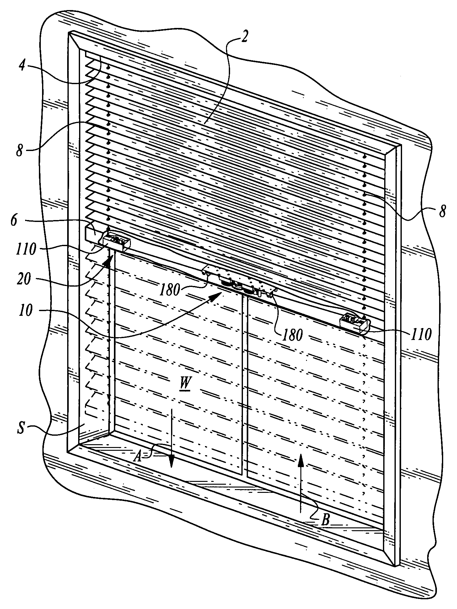
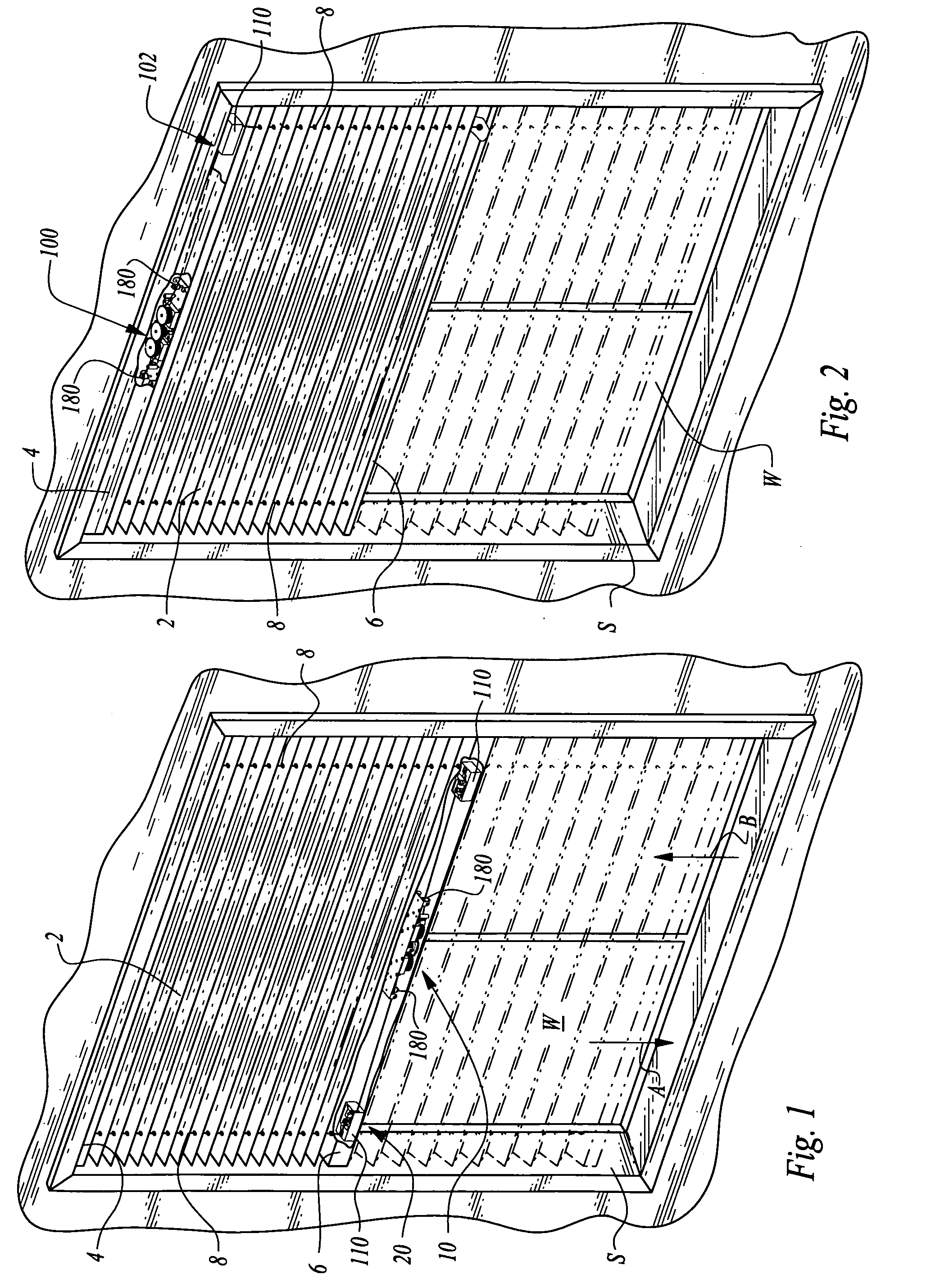
[0046]Referring to the drawings, wherein like reference numerals represent like parts throughout the various drawing figures, reference numeral 10 (FIGS. 1 and 3-5) is directed to a lifting mechanism for a window covering 2. The window covering 2 generally includes a top rail 4 parallel with and spaced from a bottom rail 6 with a window covering material structure extending between the top rail 4 and bottom rail 6.

[0047]Cords 8 extend between the top rail 4 and the bottom rail 6. The lifting mechanism 10 acts upon the cords 8 within one of the rails 4, 6 so that the bottom rail 6 can maintain equilibrium wherever the bottom rail 6 is positioned by a user. In this way, a user can raise the bottom rail 6 (arrow B of FIG. 1) or lower the bottom rail 6 (arrow A of FIG. 1) to expose the window W or occlude the window W, with the bottom rail 6 conveniently remaining where it is left by the user.

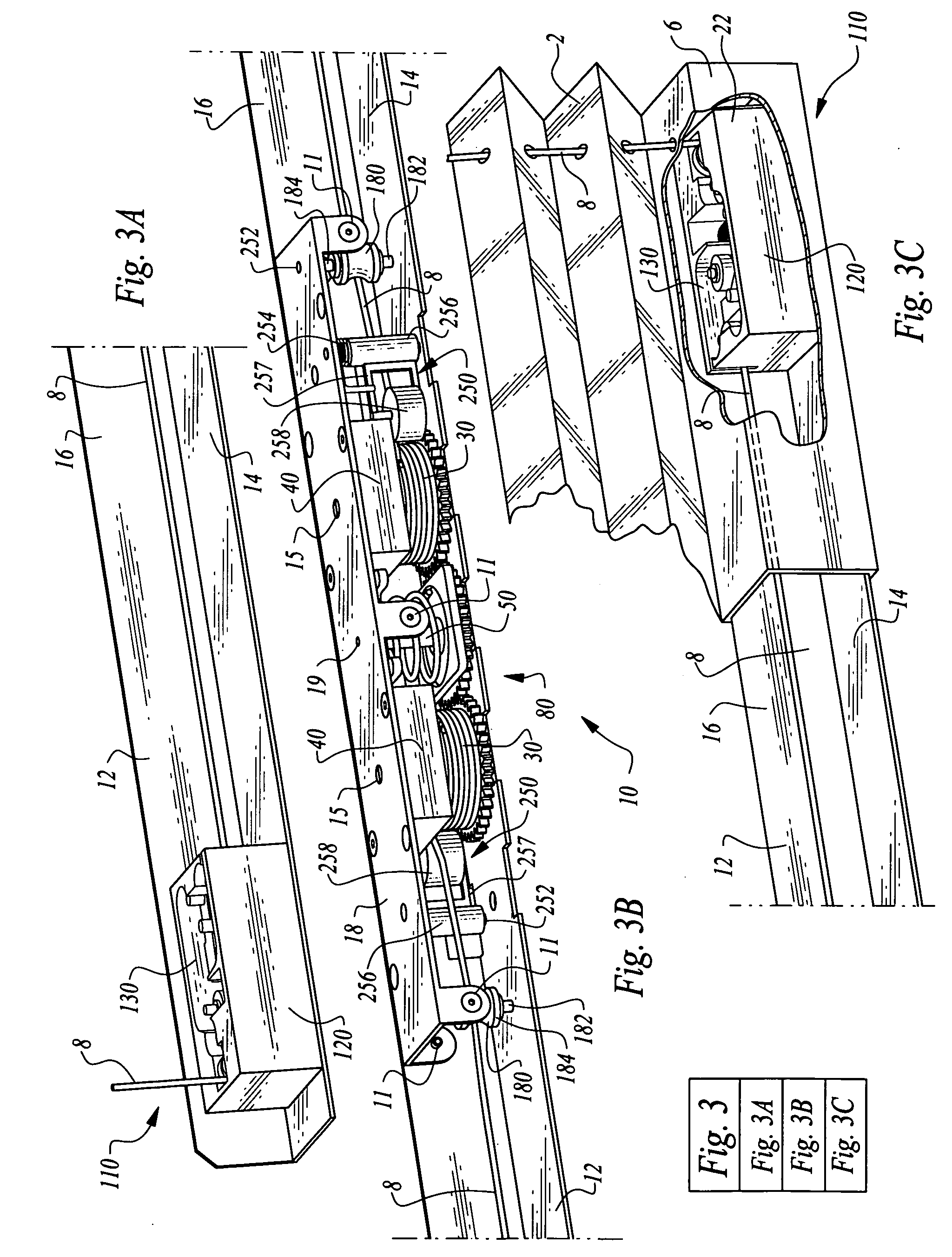
[0048]In essence, and with particular reference to FIGS. 1 and 3-5, basic details of the liftin...


PUM


Abstract

A lifting mechanism is provided for a window covering which allows a bottom rail of the window covering to maintain a static position unless raised or lowered by a user. The lifting mechanism is included within either a top or bottom rail of the window covering. The lifting mechanism includes cords which pass from a rail including the lifting mechanism to the opposite rail, about cord redirecting tension sensors along the cord. The lifting mechanism includes spools and associated springs for gathering excess portions of the cord. A progressive resister is coupled to the spools to provide different amounts of resistance to spool rotation depending on the amount of cord upon each spool. The tension sensors sense cord tension and lock the cord when only tension associated with gravity is sensed and release the cord when elevated or reduced tension associated with lifting or lowering the bottom rail is sensed.

Description

FIELD OF THE INVENTION[0001]The following invention relates to lifting mechanisms for window coverings. More particularly, this invention relates to lifting mechanisms for window coverings which automatically provide sufficient lifting force so that a bottom rail of the window covering will remain in a position where it is placed by a user until the bottom rail is again moved by a user to a new position, without requiring manipulation of locking mechanisms, such as buttons, cords or other manually actuated locking mechanisms.BACKGROUND OF THE INVENTION[0002]Window coverings are provided in a wide variety of styles and configurations to both provide the function of at least partially occluding the passage of light through a window and enhancing an appearance of a room in which the window is located. Such window coverings can include shades which are typically continuous from a top rail at an upper end of the window covering that is typically affixed adjacent an upper end of the windo...

Claims


Application Information

Patent Timeline
IPC IPC(8): E06B9/30A47H7/00
CPCE06B2009/3222E06B9/30
Inventor SHEVICK, BARRY L.
Owner SHADES UNLTD
Why Eureka
Try Eureka