Pitcher Lid with Spout Gate and Stirring Mechanism
- Summary
- Abstract
- Description
- Claims
- Application Information
AI Technical Summary
Benefits of technology
Problems solved by technology
Method used
Image

Examples
first embodiment
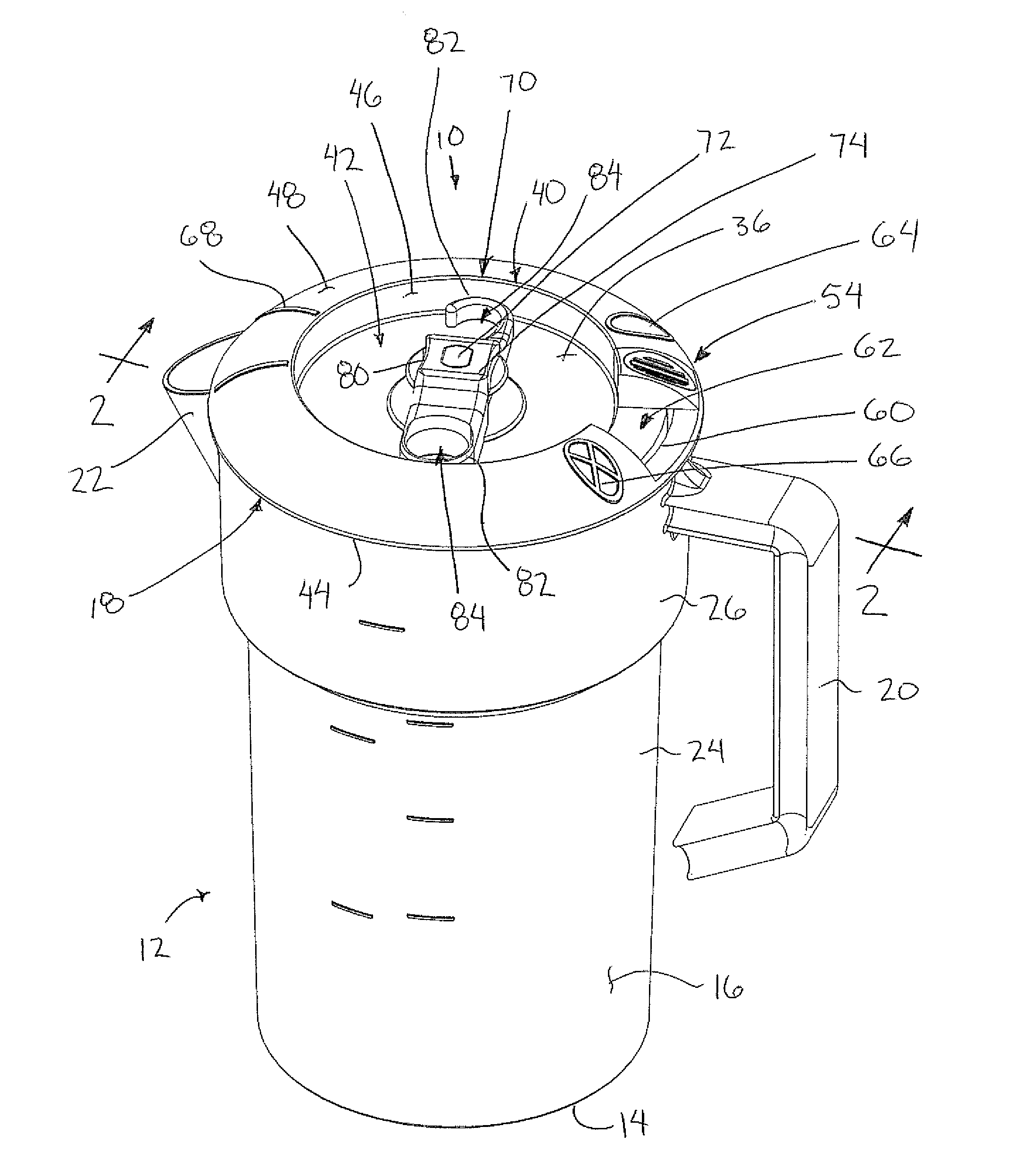
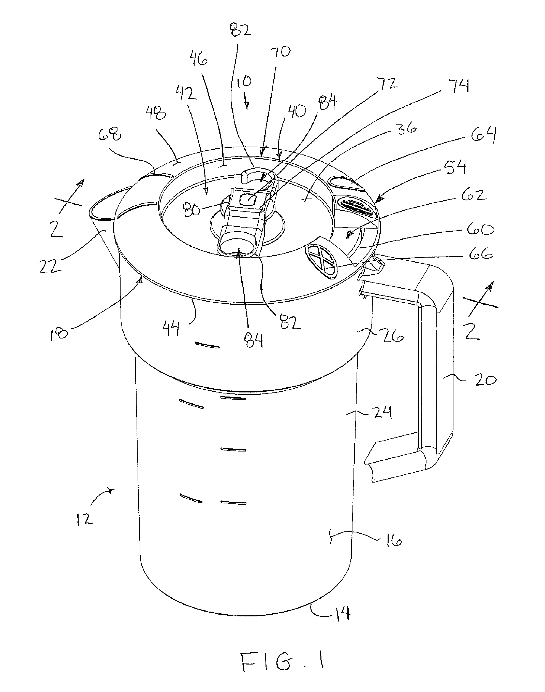
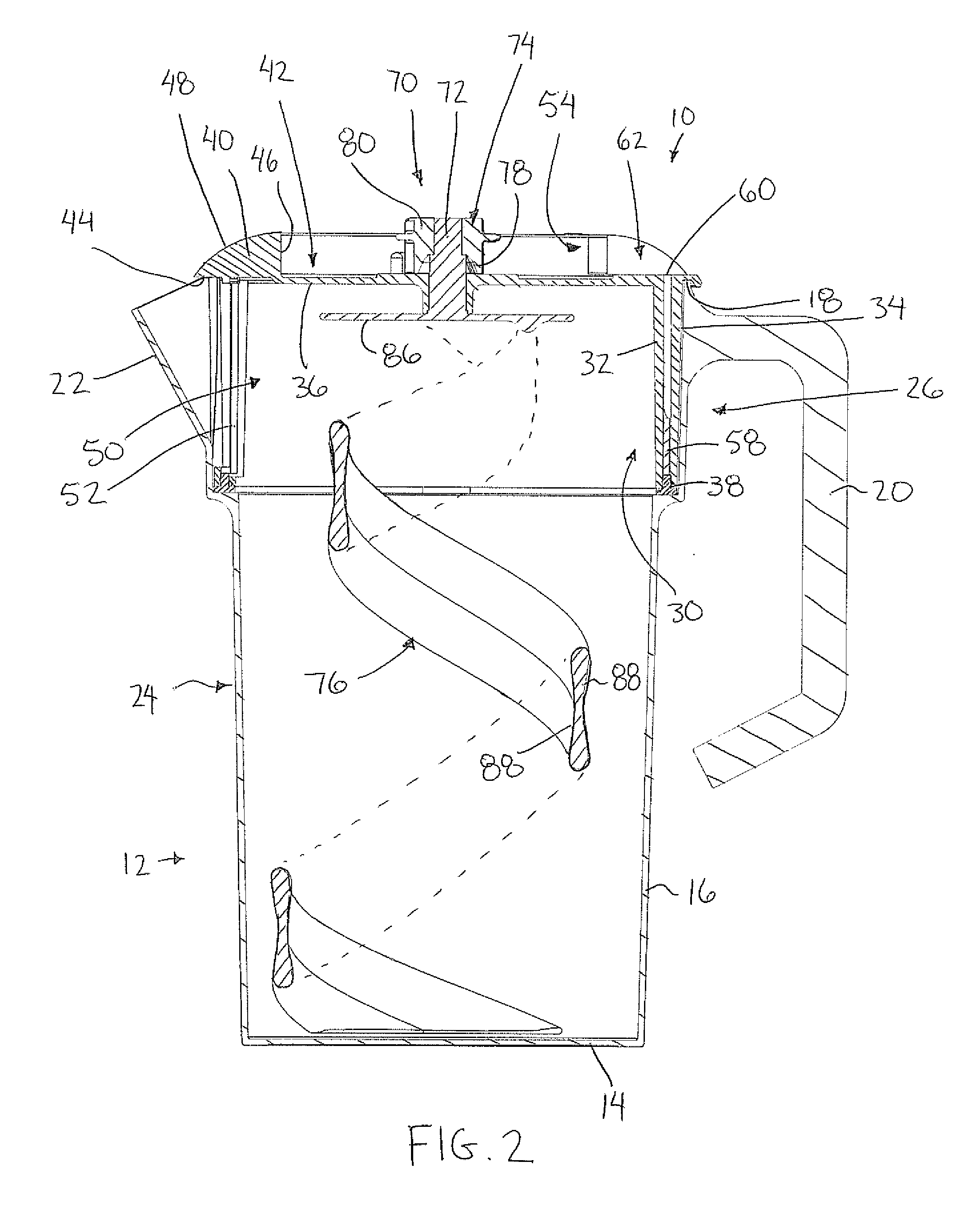
[0053]Turning to FIGS. 1 through 6, the lid comprises a lid body 30 having an inner cylindrical wall 32 and an outer cylindrical wall 34. The inner cylindrical wall 32 is concentric with the outer cylindrical wall and spaced inward therefrom so that the walls are substantially parallel with one another and spaced apart to define an annular gap therebetween. The overall thickness of the inner and outer walls together with the gap therebetween in the radial direction is approximately equal to the difference in interior diameter between the upper and lower portions of the wall of the pitcher body at the shoulder with the outer cylindrical wall fitting closely within the interior diameter of the upper portion 26 of the pitcher such that the inner diameter of the inner cylindrical wall 32 is approximately equal to the inner diameter of the lower pitcher adjacent the top end thereof. Accordingly the inside surface of the wall of the lid is substantially flush with the inside surface of th...
second embodiment
[0075]The second embodiment is further distinguished from the previous embodiment in that the lid body only comprises the outer cylindrical wall 34 with no additional inner wall being provided so that the gate member is supported along the inner surface of the lid body. The gate member 52 in this instance comprises a cylindrical upright wall which extends about the full circumference of the lid body with an outer diameter corresponding approximately to the inner diameter of the lid body for being slidably received therein. The overall lid assembly including the outer cylindrical wall 34 of the lid body and the gate member along the inner surface thereof thus have a smaller thickness in the radial direction than the previous embodiment so that the shoulder formed in the pitcher wall between the upper and lower portions thereof can be reduced in relation to the previous embodiment.
[0076]The gate member 52 of the second embodiment is further distinguished in locating a gate opening 102...
PUM
 Abstract
Description
Claims
Application Information
 - Generate Ideas
- Intellectual Property
- Life Sciences
- Materials
- Tech Scout
- Unparalleled Data Quality
- Higher Quality Content
- 60% Fewer Hallucinations
Browse by: Latest US Patents, China's latest patents, Technical Efficacy Thesaurus, Application Domain, Technology Topic, Popular Technical Reports.
© 2025 PatSnap. All rights reserved.Legal|Privacy policy|Modern Slavery Act Transparency Statement|Sitemap|About US| Contact US: help@patsnap.com