Method and system for selecting the viewing configuration of a rendered figure

a technology of viewing configuration and method, applied in the field of method and system for determining the viewing configuration of a rendered figure, can solve problems such as inability to select the optimal viewing configuration

Active Publication Date: 2010-08-19
KONINKLIJKE PHILIPS ELECTRONICS NV
View PDF23 Cites 11 Cited by
  • Summary
  • Abstract
  • Description
  • Claims
  • Application Information

AI Technical Summary

Benefits of technology

[0023]It is extremely advantageous for a rehab-patient or a sports trainee that the feedback is given as an automatically chosen viewing configuration, without any need for input from the patient.

Problems solved by technology

A problem experienced with the existing external feedback systems is that the viewing configuration, i.e. the rotation, tilt, zoom, and eventual other parameters, is still to be determined by the patient or the therapist, or in case of a sports teaching situation, by the trainee or the coach.
However, in this known system, the viewer still needs to be aware about the best viewport or, in other systems, the viewer is restricted to certain, pre-defined viewing setups that can be selected on demand.
Since patients usually lack the expertise and additionally are cognitively impaired, they are in general not able to select the optimal viewing configuration.

Method used


Image

  • Method and system for selecting the viewing configuration of a rendered figure
  • Method and system for selecting the viewing configuration of a rendered figure
  • Method and system for selecting the viewing configuration of a rendered figure

Examples


fourth embodiment

[0043]In a fourth embodiment, the identification of motion parameters is not limited to a single motion parameter but a collection of motion parameters. Thus, taking multiple motion parameters into account, if 4 motion parameters in total would be considered to be relevant, but the top candidate stands separate while the other 3 motion parameters are related, the 3 motion parameters might be selected as being the relevant ones.

fifth embodiment

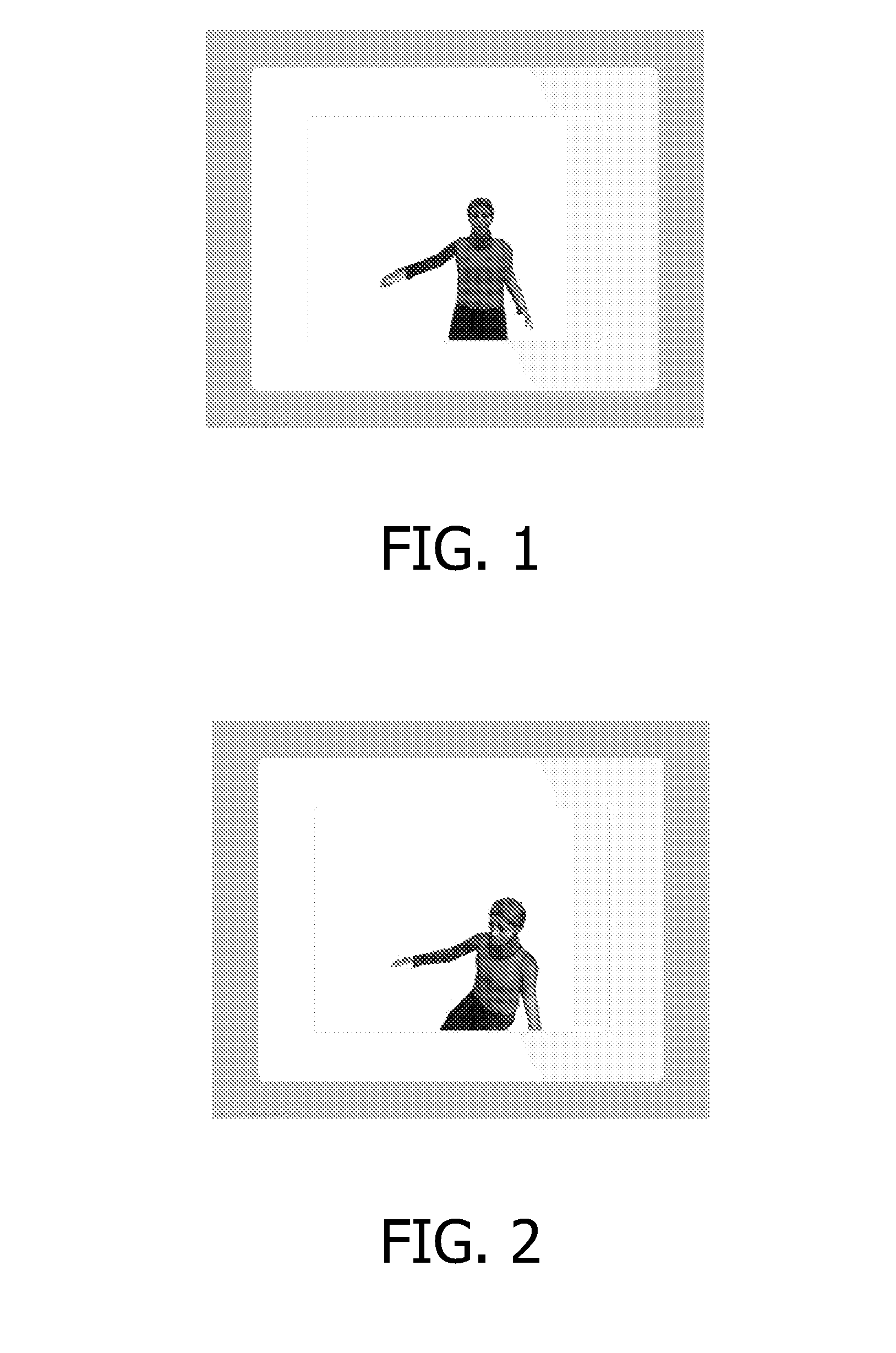
[0044]In a fifth embodiment, the identification of the most relevant motion parameters is not limited to a small time-window but takes the context into account. For example, if mostly the sagittal plane is considered to be relevant and, within short fragments, the frontal plane is identified, the context could be used to stick to a viewing configuration that allows the optimal analysis of movements in the sagittal plane. This smoothes the display of the avatar and prevents too many changes in the view on the figure.

sixth embodiment

[0045]In a sixth embodiment, multiple avatars might be used to deliver an optimal view on the avatar. Due to the identified motion parameters, two or more avatars re-playing the patient's movements and being shown from different perspectives provide more insight on the region of interest than a single avatar. The optimal number of avatars may depend on the identified motion parameters.


PUM


Abstract

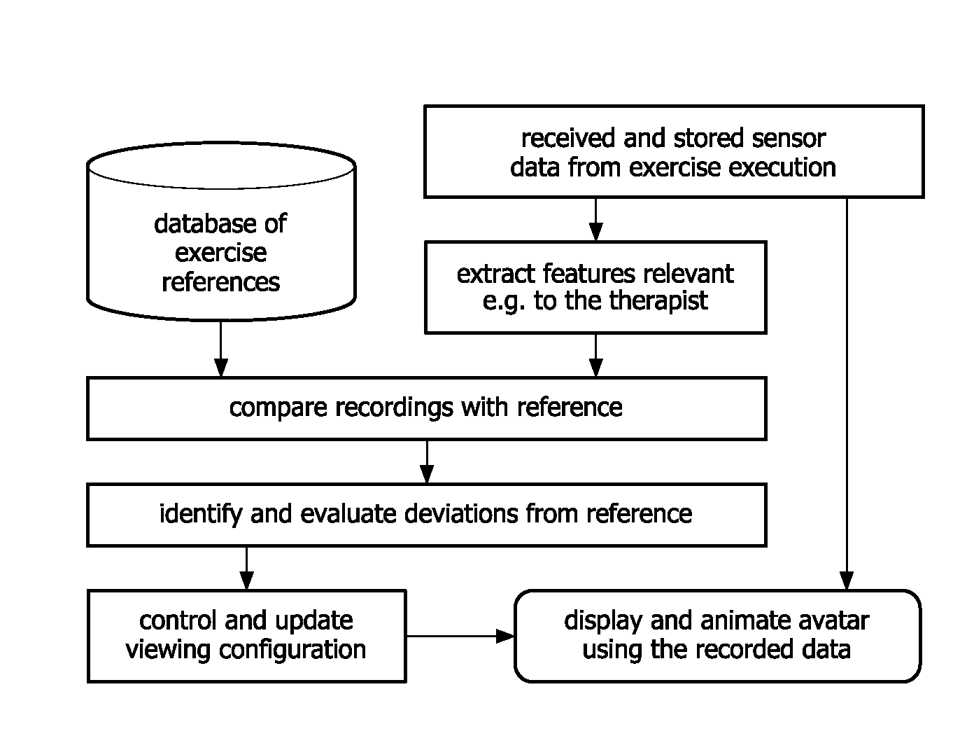
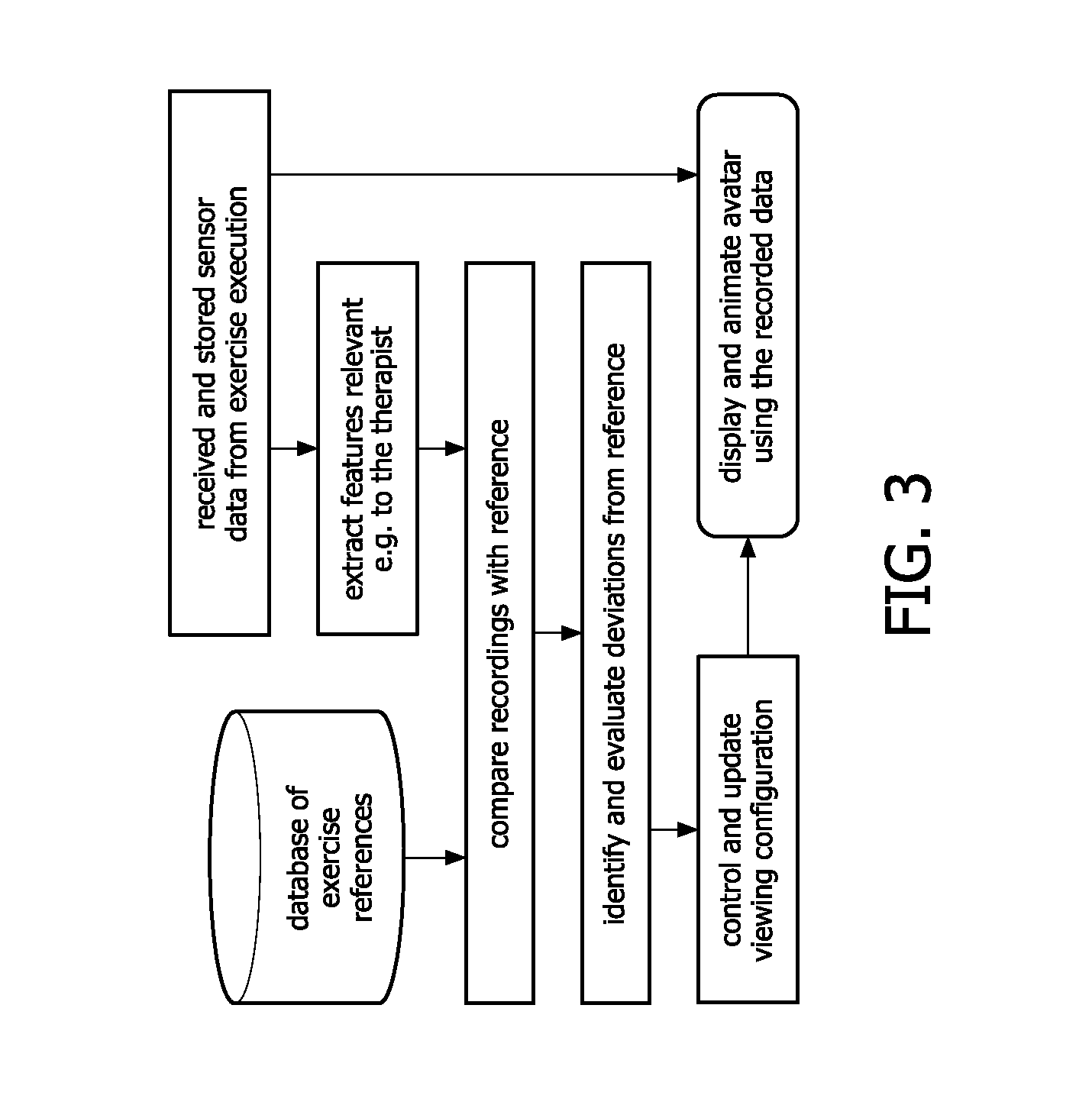
A method for determining a viewing configuration of a rendered figure of a rehab-patient or a sports trainee, aiming to deliver a suitable view on the rendered figure, the method comprising the steps of capturing motion data in the 3D space of one or more body parts of the rehab-patientor the sports trainee and providing them to a computer; and further the step of performing on the computer measurements of deviation of the captured motion data from a reference list of motion data and / or measurements of main motion direction; and based on the results of the above measurements, determining the viewing configuration.

Description

FIELD OF THE INVENTION[0001]The present invention relates to a method and a system for determining a viewing configuration of a rendered figure, for example of a person of whom posture analysis or analysis of his movements is desired.[0002]In particular, the present invention relates to a method for automatically selecting one of more suitable viewing configurations of rendered images made from a person following rehabilitation therapy, a so called rehab-patient, for giving visual feedback to a therapist or to the rehab-patient.BACKGROUND OF THE INVENTION[0003]Stroke is the most prominent cause of permanent disability in the industrialized countries. One of the most prominent disabilities stroke survivors suffer from is half sided paralysis of the upper limbs. Rehabilitation exercises are proven to be efficient in regaining motor control, provided the training is intense and the patient is guided in the therapy.[0004]Technical solutions for unsupervised home stroke rehabilitation re...

Claims


Application Information

Patent Timeline
Patent Type & Authority Applications(United States)
IPC IPC(8): G06K9/00G06T15/20
CPCA63B24/0003G09B19/0038A63B69/00A63B2024/0012A63B2071/0636A63B2071/0647A63B2220/34A63B2220/40A63B2220/803A63B2220/806A63B2225/50G06T7/20G06T15/20G06T2207/30004A63B24/0006G06T2207/10016
Inventor TE VRUGT, JUERGENWILLMANN, RICHARD DANIELLANFERMANN, GERDWINTER, STEFANSAINI, PRIVENDER KAURTIMMERMANS, ANNICK
Owner KONINKLIJKE PHILIPS ELECTRONICS NV
Why Eureka
Try Eureka