Evacuation apparatus

a technology of evacuating apparatus and auxiliary components, which is applied in the direction of machines/engines, liquid fuel engines, positive displacement liquid engines, etc., can solve the problems of large volume of evacuating, increased power consumption, and operation failur

Inactive Publication Date: 2010-08-19
EBARA CORP
View PDF16 Cites 10 Cited by
  • Summary
  • Abstract
  • Description
  • Claims
  • Application Information

AI Technical Summary

Benefits of technology

[0007]The present invention has been made in view of the above drawbacks. It is therefore an object of the present invention to provide an evacuation apparatus which can evacuate a large quantity of a gas and can prevent a motor thereof from being overloaded.
[0010]According to the present invention, even in a case where the axial width of the rotor (the inlet-side rotor) of the first vacuum pump is designed to be large, a load on a motor of the first vacuum pump can be small. Therefore, a pumping speed (l / min, a volume of a gas evacuated per unit time) can be large, and hence a large quantity of gas can be evacuated.
[0014]According to the present invention, the multistage pump rotors can be prevented from expanding due to heat of compression of the gas and heat of the motor. Therefore, it is possible to prevent the multistage pump rotors from being brought into contact with an inner surface of the rotor casing. Further, the motor can be prevented from being overloaded, and hence heat generation and the power consumption of the motor can be reduced.

Problems solved by technology

However, as a substrate such as a semiconductor wafer or a liquid crystal panel, which is an object to be processed, becomes large in size, there has been an increasing need for evacuating a large quantity of the process gas.
However, with such a structure, a motor for driving the booster pump is overloaded, resulting in increased power consumption.
In addition, the pump rotors are likely to expand due to heat of compression of the process gas and heat generated by the motor, and hence the pump rotors may be brought into contact with the inner surface of the rotor casing, resulting in operation failure.
Accordingly, it is difficult for the conventional evacuation apparatus having the single-stage booster pump to evacuate a large quantity of the process gas while maintaining a vacuum state in the vacuum chamber.

Method used


Image

  • Evacuation apparatus
  • Evacuation apparatus
  • Evacuation apparatus

Examples


Embodiment Construction

[0022]An evacuation apparatus according to an embodiment of the present invention will be described below with reference to the drawings.

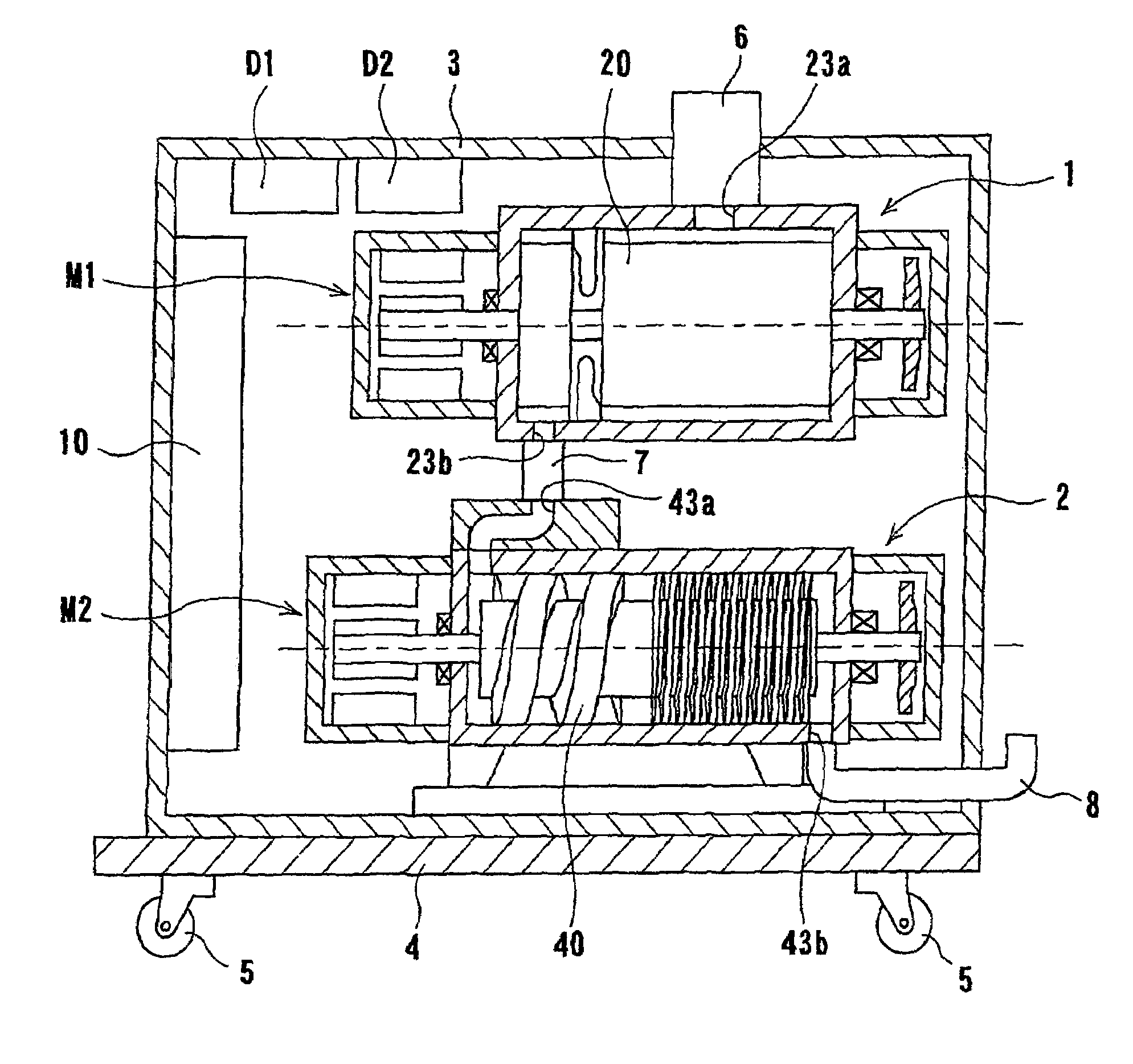
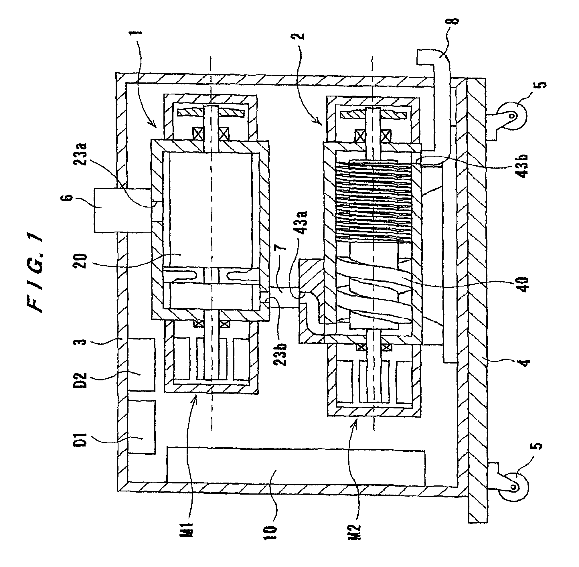
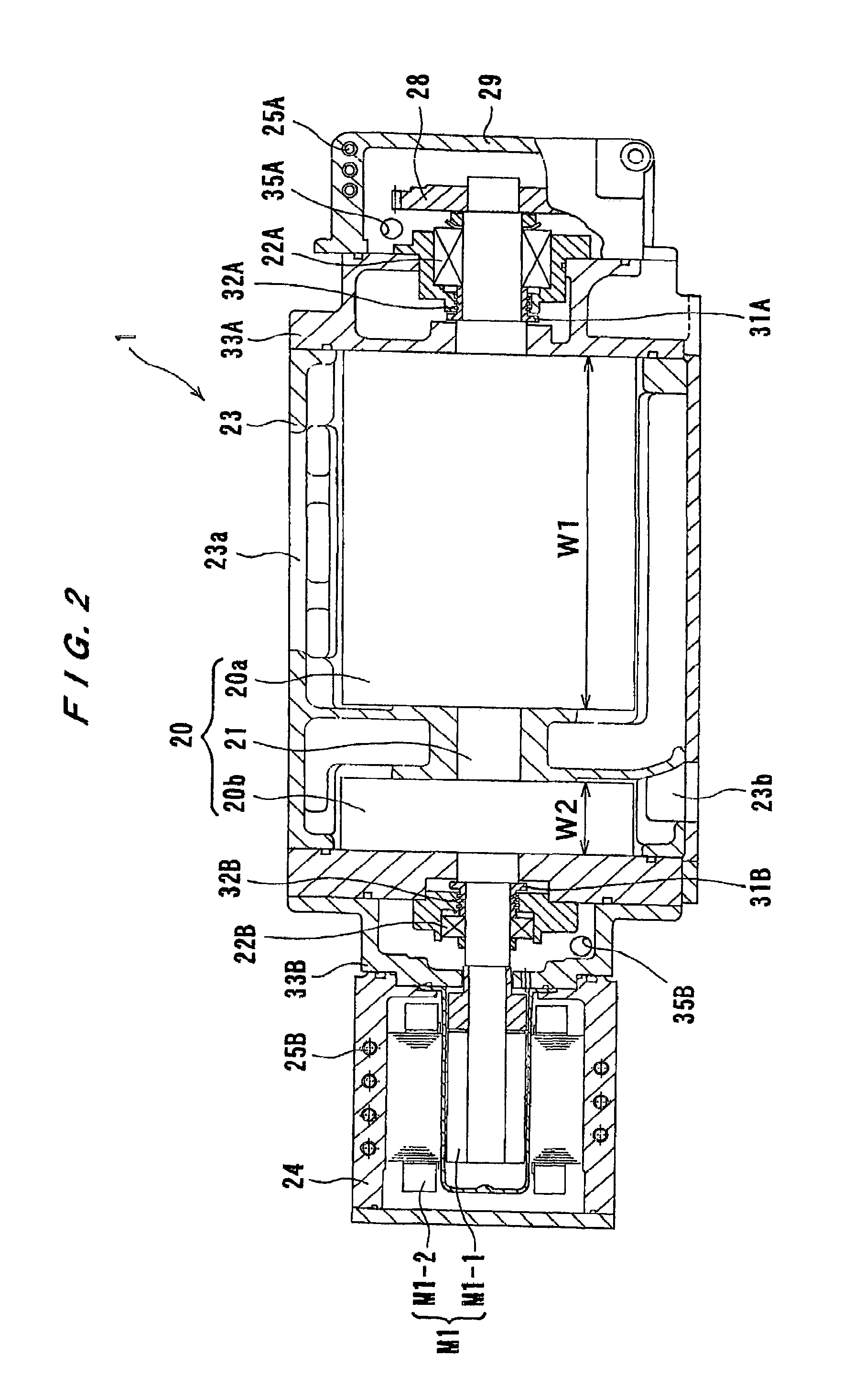
[0023]FIG. 1 is a side view showing an evacuation apparatus according to the embodiment of the present invention. FIG. 2 is a cross-sectional view showing a first vacuum pump shown in FIG. 1. FIGS. 3A through 3D are schematic views illustrating the manner in which a gas is delivered.

[0024]As shown in FIG. 1, the evacuation apparatus comprises a first vacuum pump 1 serving as a booster pump, a second vacuum pump 2 serving as a main pump, and a housing (an enclosure) 3 for accommodating the first vacuum pump 1 and the second vacuum pump 2 therein. The housing 3 is fixed to an upper surface of a bottom plate 4, and the second vacuum pump 2 is installed on this bottom plate 4. Four wheels 5 (two of which are shown in FIG. 1) are fixed to a lower portion of the bottom plate 4, thus allowing the evacuation apparatus to be transportable.

[0025]The first va...


PUM

PropertyMeasurementUnit
of timeaaaaaaaaaa
currentaaaaaaaaaa
rotational speedaaaaaaaaaa

Abstract

The present invention relates to an evacuation apparatus for evacuating a vacuum chamber of a substrate processing apparatus for processing a substrate such as a semiconductor wafer or liquid crystal panel. An evacuation apparatus according to the present invention includes a first vacuum pump connected to a vacuum chamber, and a second vacuum pump connected to the first vacuum pump. The first vacuum pump has a pair of multistage pump rotors.

Description

CROSS-REFERENCE TO RELATED APPLICATIONS[0001]This application is a division of U.S. application Ser. No. 10 / 563,255, filed on Jun. 9, 2006, which is a 371 of International Application No. PCT / JP2004 / 015563 filed on Oct. 14, 2004, which is based upon and claims the benefit of priority from the prior Japanese Patent Application No. 2003-358424, filed on Oct. 17, 2003, the entire contents of which are incorporated herein by reference.TECHNICAL FIELD[0002]The present invention relates to an evacuation apparatus for evacuating a vacuum chamber of a substrate processing apparatus.BACKGROUND ART[0003]An evacuation apparatus is widely used for evacuating a process gas that has been supplied to a vacuum chamber of a substrate processing apparatus. In this substrate processing apparatus such as a CVD apparatus or an etching apparatus, it is required to evacuate the process gas from the vacuum chamber to produce a constant vacuum state therein, and a plurality of vacuum pumps connected in seri...

Claims


Application Information

Patent Timeline
Patent Type & Authority Applications(United States)
IPC IPC(8): F04C14/02F04C11/00C23C16/44F04B49/06F04C18/00F04C18/12F04C18/16F04C21/00F04C23/00F04C25/02F04C28/02F04C28/08F04C29/00
CPCC23C16/4412F04C18/126F04C18/16F04C23/001F01C21/007F04C25/02F04C28/08H01J37/32834F04C23/005
Inventor KAWAMURA, TAKESHIKAGAWA, KOICHI
Owner EBARA CORP
Why Eureka
Try Eureka