Bike pedal assembly structure

a technology of assembly structure and pedal, which is applied in the direction of mechanical control devices, process and machine control, instruments, etc., can solve the problems of not being able to bend the pedal, complicated structure and laborious operation, and the assembly structure of prior art pedals is far from ideal for us

Inactive Publication Date: 2010-08-26
WANG CHUNG HAN
View PDF18 Cites 3 Cited by
  • Summary
  • Abstract
  • Description
  • Claims
  • Application Information

AI Technical Summary

Benefits of technology

[0007]The objective of this invention is to provide a bike pedal assembly structure which is handy in dismounting the pedal from the crank.

Problems solved by technology

However, the means to bend the pedal has disadvantages such as complicated structure and laborious operation.
As for the situation of placing the dismounted pedal somewhere (store it), the disadvantages about it including forgetting it (taking time to find it out later on) or even losing it (couldn't find it any more), which substantially demonstrates the assembly structures of the prior art pedals are far from ideal for use.

Method used


Image

  • Bike pedal assembly structure
  • Bike pedal assembly structure
  • Bike pedal assembly structure

Examples


Embodiment Construction

[0031]To achieve the foregoing objects of the present invention, the techniques adopted and the achievable functioning are detailed described with reference to the following preferred exemplified embodiments and the accompanying drawings, which helps a thorough comprehension of the present invention.

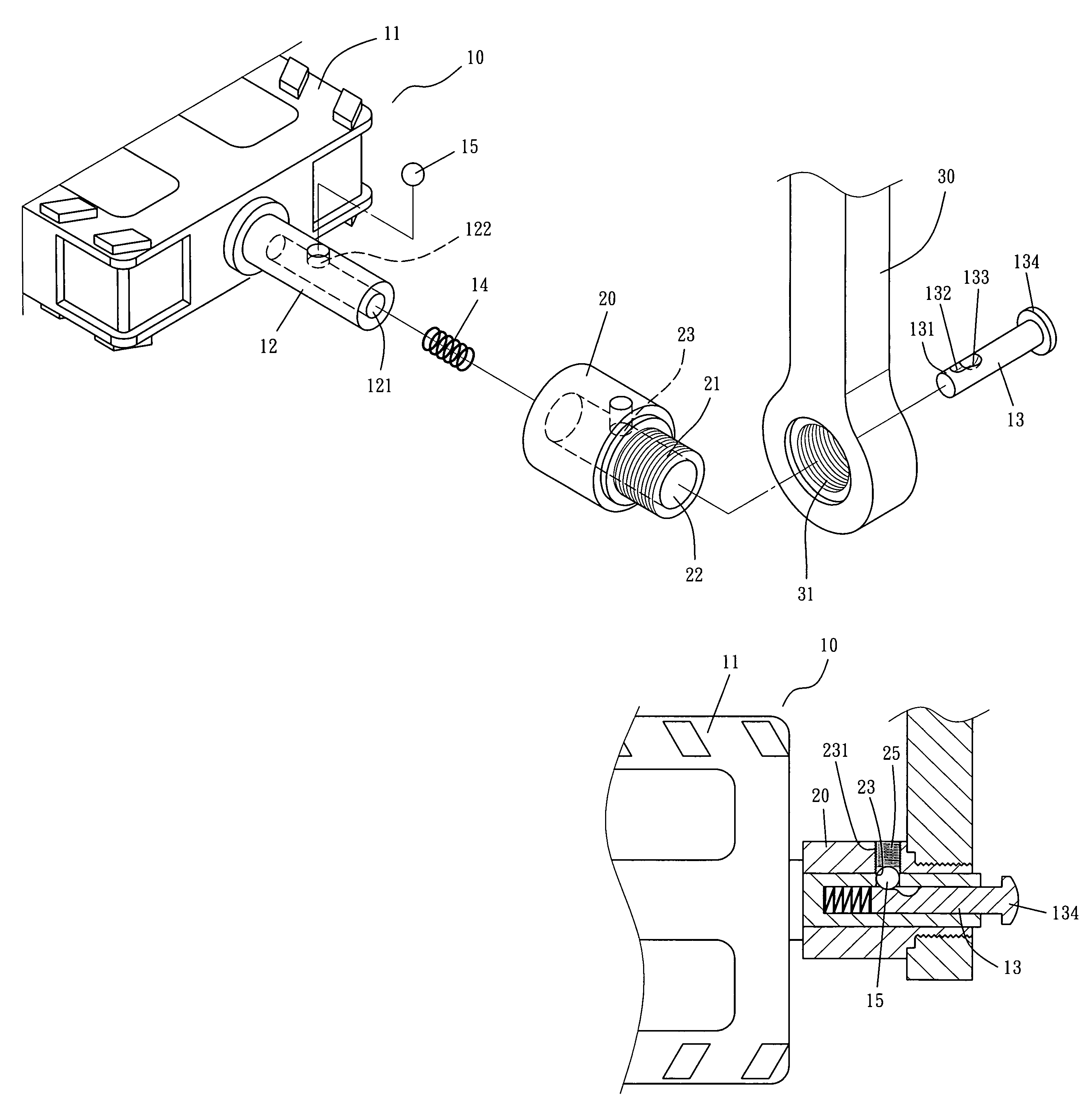
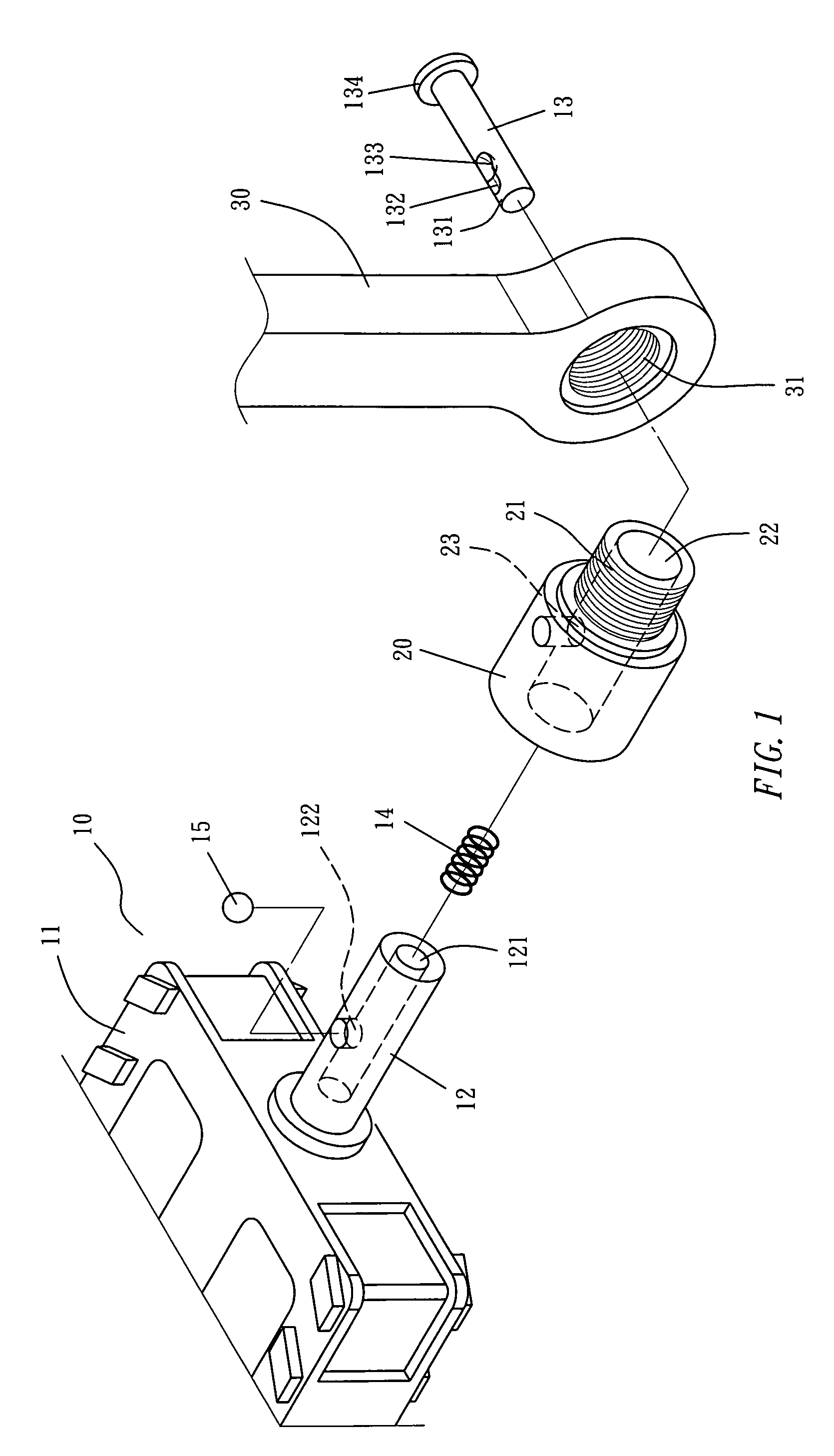
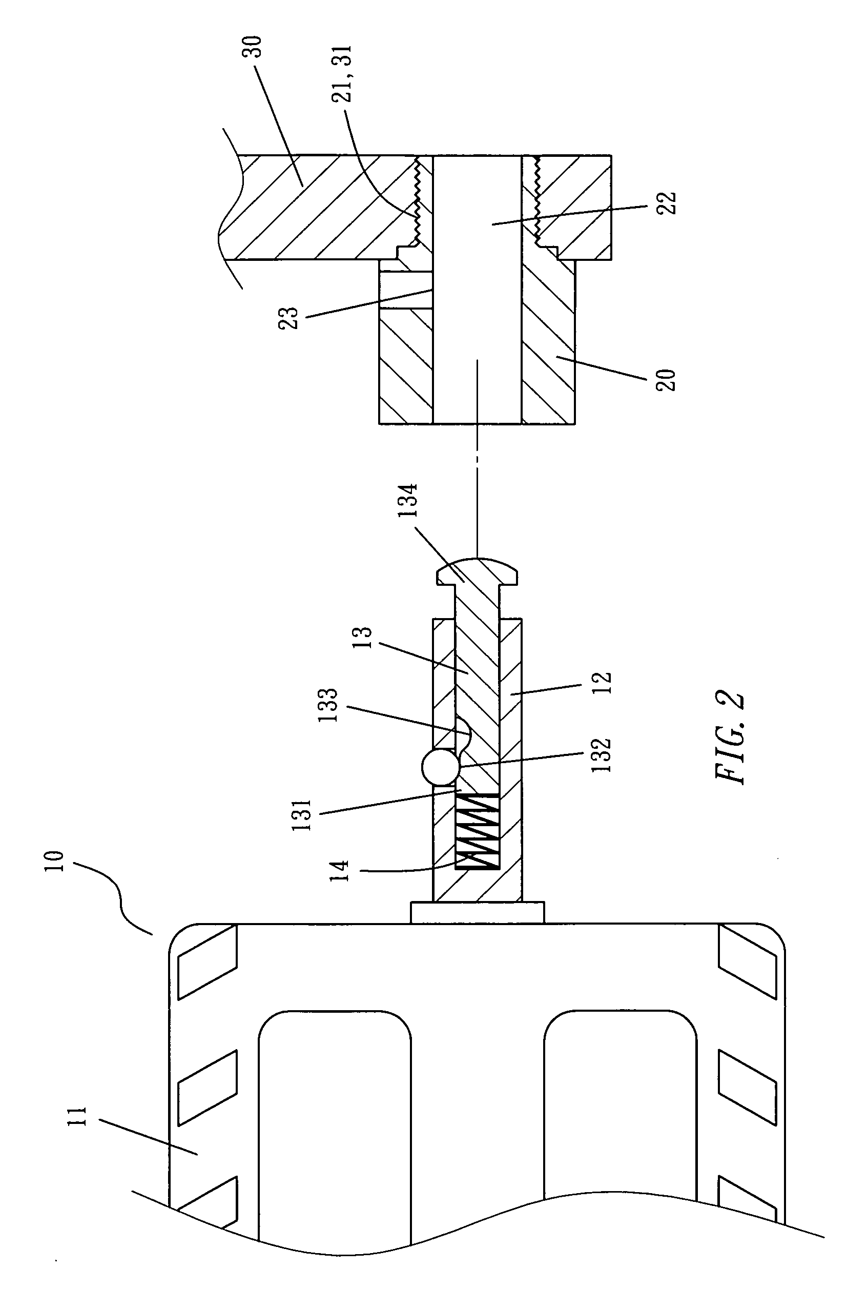
[0032]Referring to FIGS. 1 & 2, the embodiment of this invention is a bike pedal assembly structure, comprising a pedal 10, a bracing joint 20 and a crank 30; wherein the pedal 10 comprises a pedal surface 11 (may be any shape), a pivotal shaft 12 extended from a side thereto; where the pivotal shaft 12 is provided with an inward cylindrical hollow 121 and a fixing hole 122 from its inner wall through to the outside; and the pedal 10 further comprises a control bar 13, a springy member 14 (may be bar spring in shape) and a fixing member 15 (may be a spherical steel ball), where the control bar 13 is a rod that is inserted into the cylindrical hollow 121 and the rod is provided with a blo...


PUM


Abstract

A bike pedal assembly structure is disclosed, which involves a bracing joint connecting to a crank, and a pivotal shaft of the pedal and a control bar are penetrated into a joining cylinder of the bracing joint for a joining. By depressing the pressing head of the control bar, the pivotal shaft of the pedal and the control bar can be dismounted from the joining cylinder. The pedal can even be mounted to the same structure in a reverse position for the prevention of the possibilities in forgetting to place it somewhere or even in losing it. Since the store of the pedals is located at the space between the cranks of both sides, which means deadly save the space.

Description

BACKGROUND OF THE INVENTION[0001]1. Field of the Invention[0002]The present invention relates generally to a bike pedal assembly structure and more specifically to one handy in dismounting the pedal from the crank, and in mounting the pedal to the same structure in a reverse position for the prevention of the possibilities in forgetting to place it somewhere or even losing it, minimizing occupied volume and saving transport and stock space.[0003]2. Description of the Prior Art[0004]A bike pedal is a component that is mounted on the bike for being stepped by a foot to advance the bike. The common structure of the bike pedal has a “pedal surface” (can be any shape) and a “pivotal shaft” extending from its lateral. In assembly, the pivotal shaft is pin-jointed to the outer end of a crank which is extended from each of two opposite sides at front chain wheel. And the pedal surfaces are located at both sides of the bike respectively, which are perpendicular to the bike frame for the purp...

Claims


Application Information

Patent Timeline
Patent Type & Authority Applications(United States)
IPC IPC(8): G05G1/30
CPCY10T74/20888B62M3/08
Inventor WANG, CHUNG-HAN
Owner WANG CHUNG HAN
Why Eureka
Try Eureka