

Airway Devices, Tube Securing Devices, and Methods of Making and Using the Same
a technology of airway and tube, which is applied in the field of airway devices and tube securing devices, and the methods of making and using the same, can solve the problems of affecting the health of patients, affecting the patient's health, and often failing to visualize the glottic opening
- Summary
- Abstract
- Description
- Claims
- Application Information
AI Technical Summary
Benefits of technology
Problems solved by technology
Method used
Image

Examples
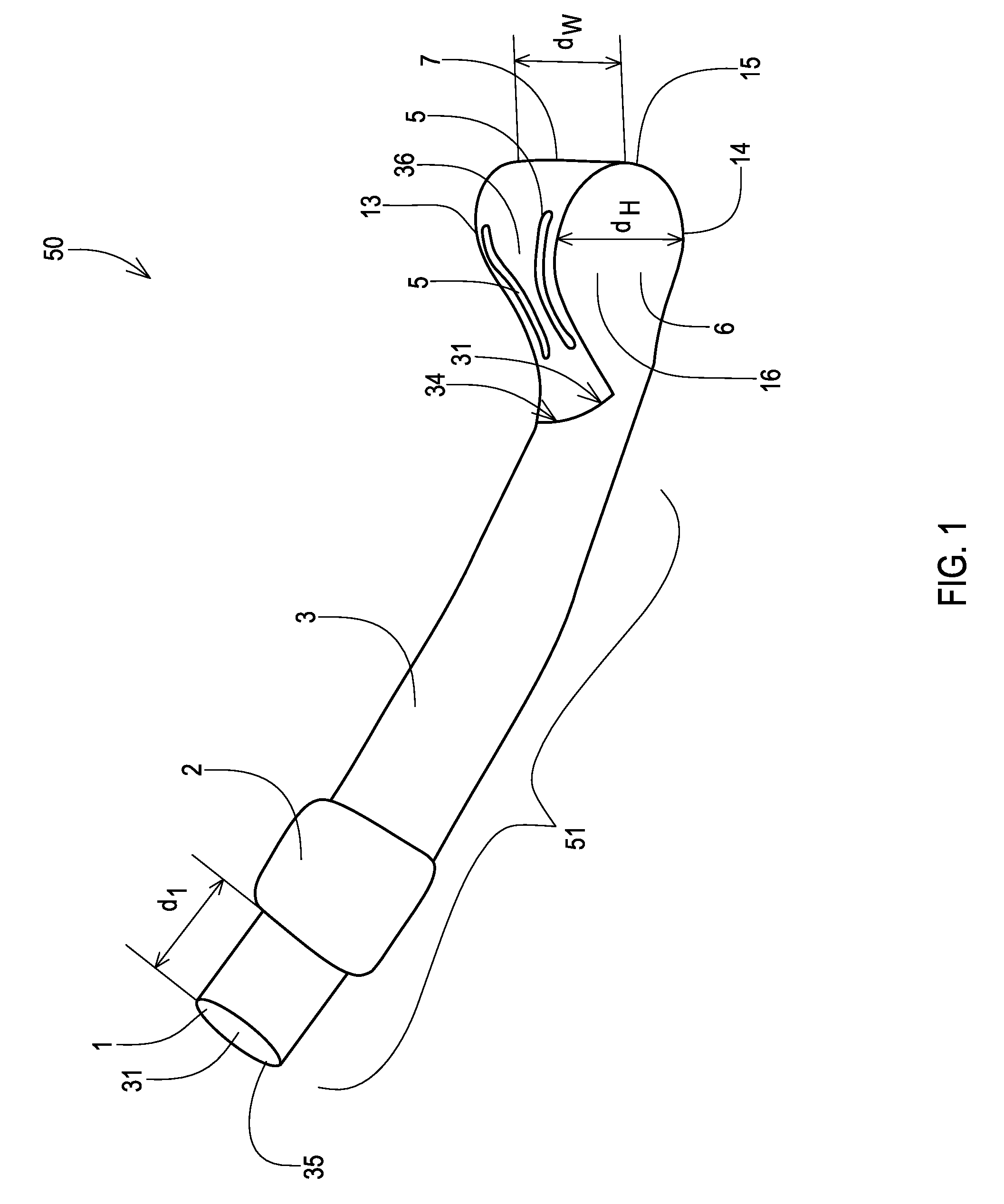
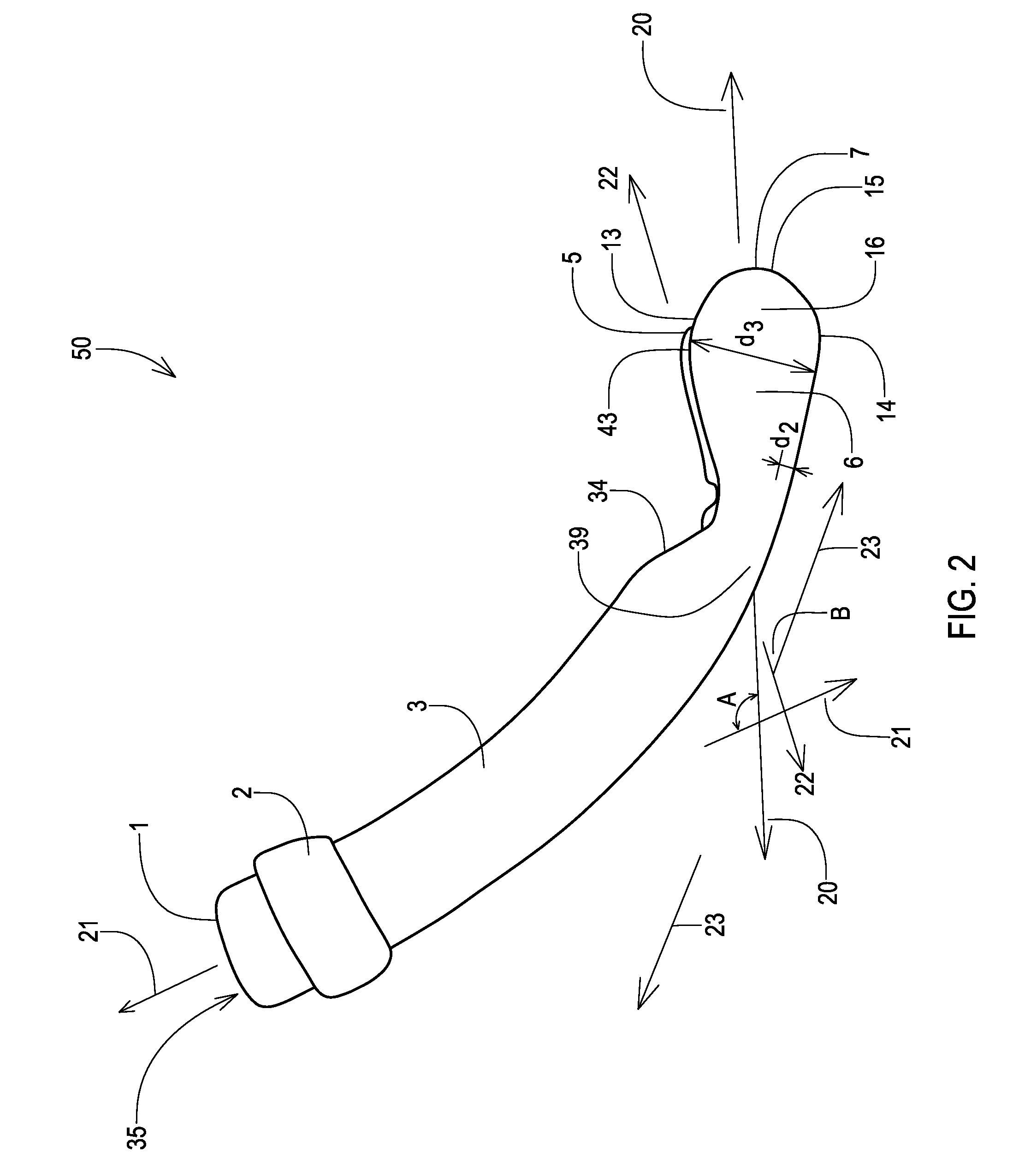
example 1
[0090]An airway device was formed via an injection molding step in which medical grade polyvinyl chloride was molded into a shape as shown in FIGS. 1-3. The resulting airway device had the following dimensions:
[0091]length=16.5 cm (6.5 in)
[0092]width of distal end=3.49 cm (1.375 in)
[0093]height of distal end=2.22 cm (0.875 in)
[0094]inner diameter=2.22 cm (0.875 in)
[0095]outer diameter=3.18 cm (1.25 in)
[0096]length of depth indicator ring=2.86 cm (1.125 in)
[0097]tubular conduit wall thickness=0.48 cm (0.1875 in)
[0098]angle of curvature along device=140°
[0099]angle of inclination along distal end of device=40°.
example 2
[0100]An airway device was formed via an injection molding step in which medical grade polyvinyl chloride was molded into a shape as shown in FIGS. 6-9. The resulting airway device had the following dimensions:
[0101]length=14.5 cm (5.7 in)
[0102]width of distal end=3.65 cm (1.438 in)
[0103]height of distal end=4.44 cm (1.75 in)
[0104]inner diameter=1.59 cm (0.625 in)
[0105]outer diameter=2.22 cm (0.875 in)
[0106]length of depth indicator ring=1.11 cm (0.438 in)
[0107]tubular conduit wall thickness=0.32 cm (0.125 in)
[0108]angle of curvature along device=135°
[0109]angle of inclination along distal end of device=30°
[0110]length of epiglottis guard (gL)=3.18 cm (1.25 in).
example 3
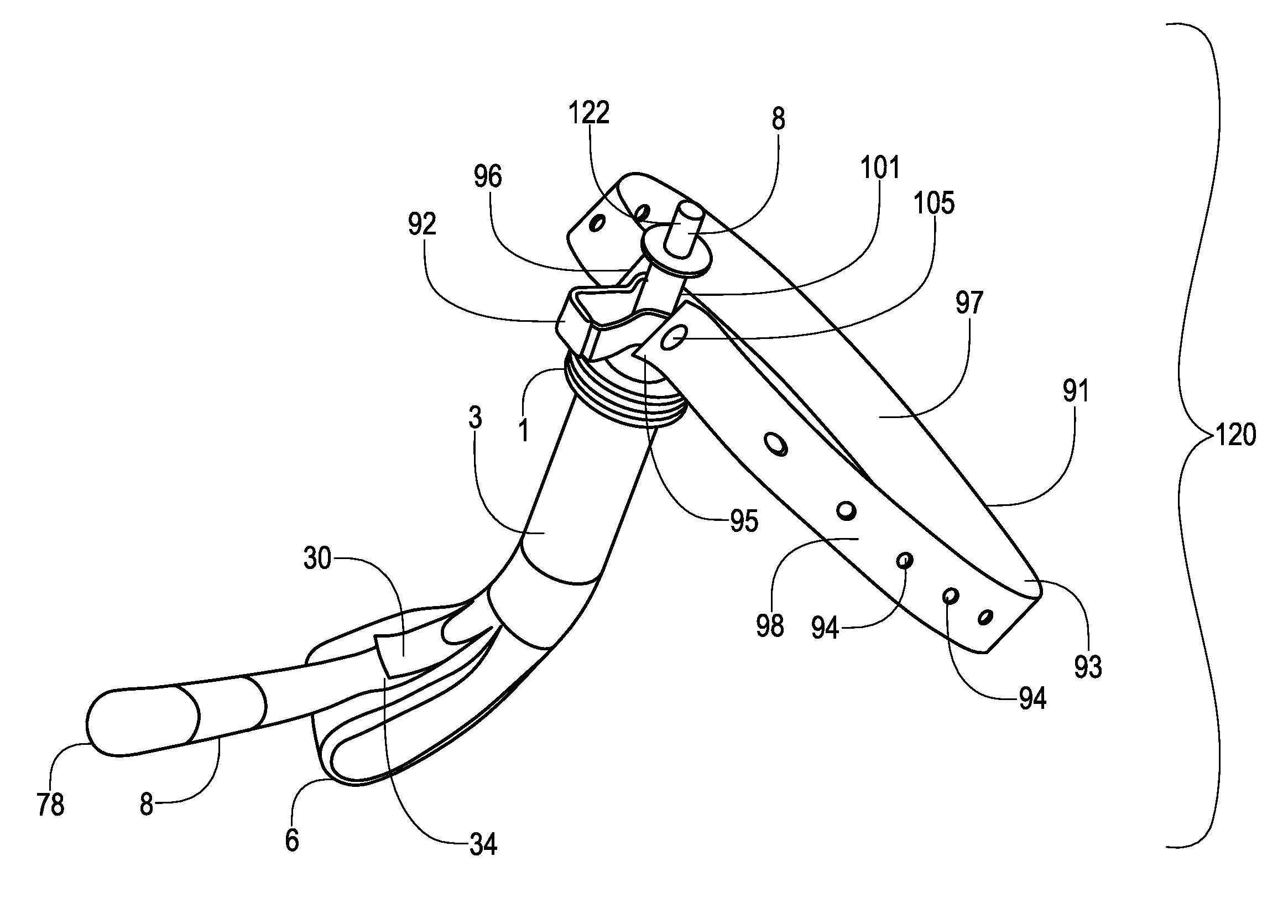
[0111]A tube securing device was formed. An endotracheal tube clamping member (e.g., exemplary endotracheal tube clamping member 92) was formed via an injection molding step in which polypropylene was molded into a shape as shown in FIGS. 11-13. The resulting endotracheal tube clamping member had the following dimensions and features:
[0112]length=3.49 cm (1.375 in)
[0113]width of closed end=2.38 cm (0.937 in)
[0114]width of open end=1.59 cm (0.625 in)
[0115]height of member=1.11 cm (0.437 in)
[0116]inner diameter of closed end=1.11 cm (0.437 in)
[0117]outer diameter of closed end=1.59 cm (0.625 in)
[0118]length of each clamp connector=0.38 cm (0.150 in)
[0119]diameter of a given clamp connector stem portion=0.32 cm (0.125 in)
[0120]overall diameter of a given clamp connector=0.83 cm (0.325 in)
[0121]approximate number of teeth in row of teeth=9.
[0122]A strap (e.g., exemplary strap 91) was formed via an extrusion step in which synthetic rubber material was extruded into a shape as shown in FI...
PUM
| Property | Measurement | Unit |
|---|---|---|
| length | aaaaa | aaaaa |
| width | aaaaa | aaaaa |
| angle | aaaaa | aaaaa |
Abstract
Description
Claims
Application Information