Modular solar racking system

a solar array and module technology, applied in the direction of rigid containers, furniture parts, packaging, etc., can solve the problems of difficult to remove if desired, difficult to meet the strength, reliability, environmental and safety standards of such installations, and the exposure of the building to the effect of a large amount of energy

Inactive Publication Date: 2010-08-26
ROTHSCHILD ELIE +2
View PDF15 Cites 77 Cited by
  • Summary
  • Abstract
  • Description
  • Claims
  • Application Information

AI Technical Summary

Problems solved by technology

These kinds of installations can cause exposure problems to the building due to the required structural penetration to secure the solar panels.
Additionally, it is difficult to remove if desired.
Although this helps in removal and minimizing surface penetrations, it is difficult

Method used


Image

  • Modular solar racking system
  • Modular solar racking system
  • Modular solar racking system

Examples


Embodiment Construction

[0033]In the following detailed description of the invention, reference is made to the drawings in which reference numerals refer to like elements, and which are intended to show by way of illustration specific embodiments in which the invention may be practiced. It is understood that other embodiments may be utilized and that structural changes may be made without departing from the scope and spirit of the invention.

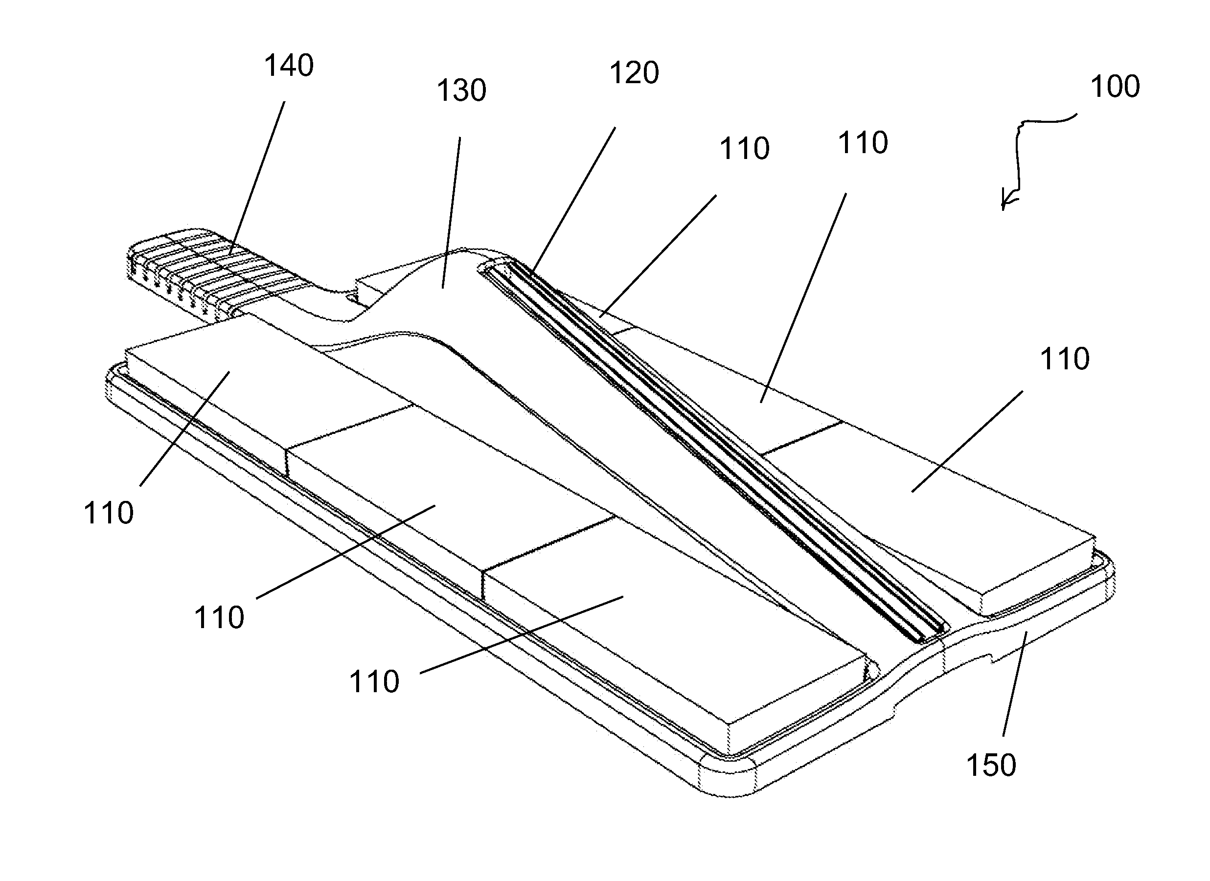
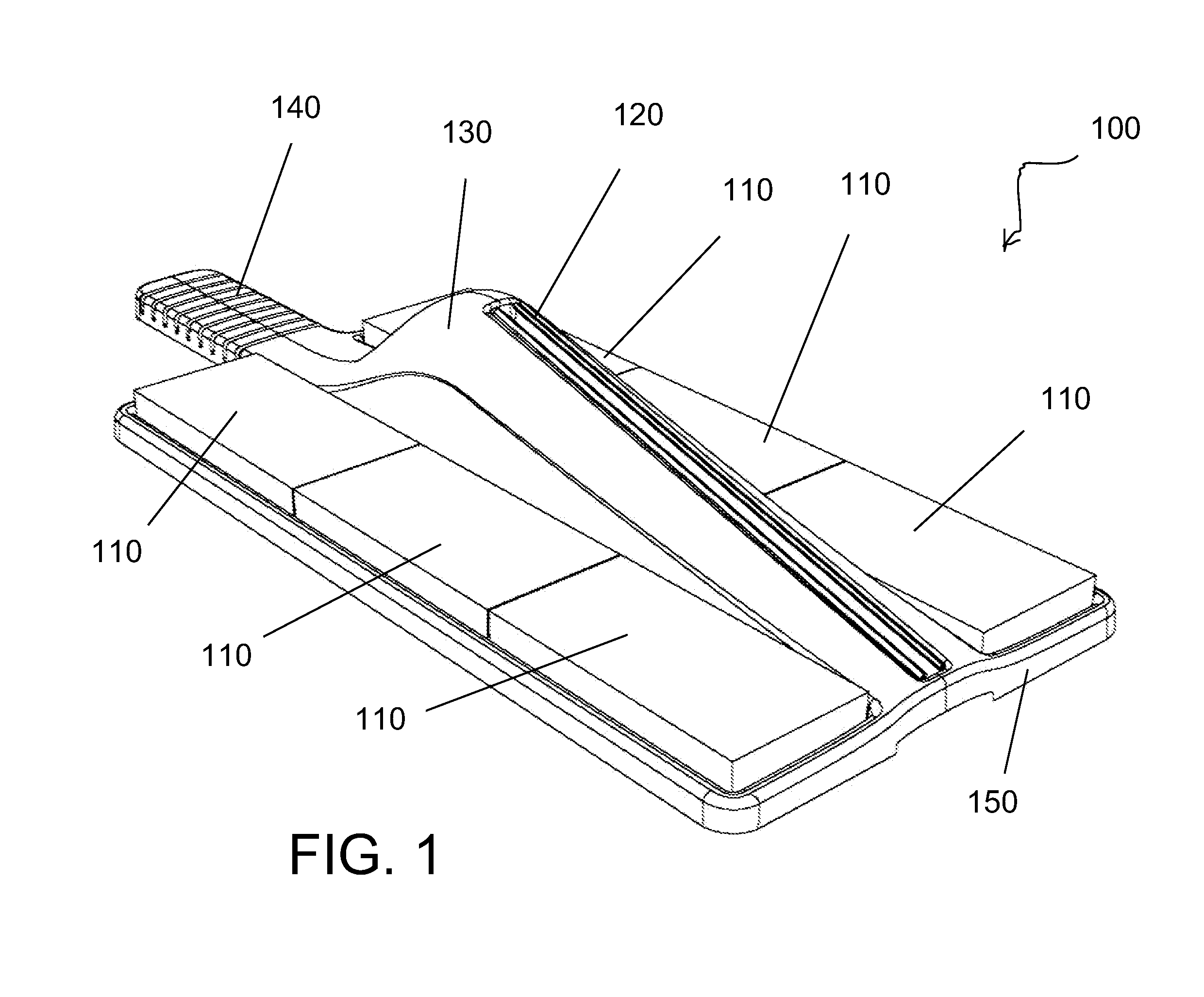
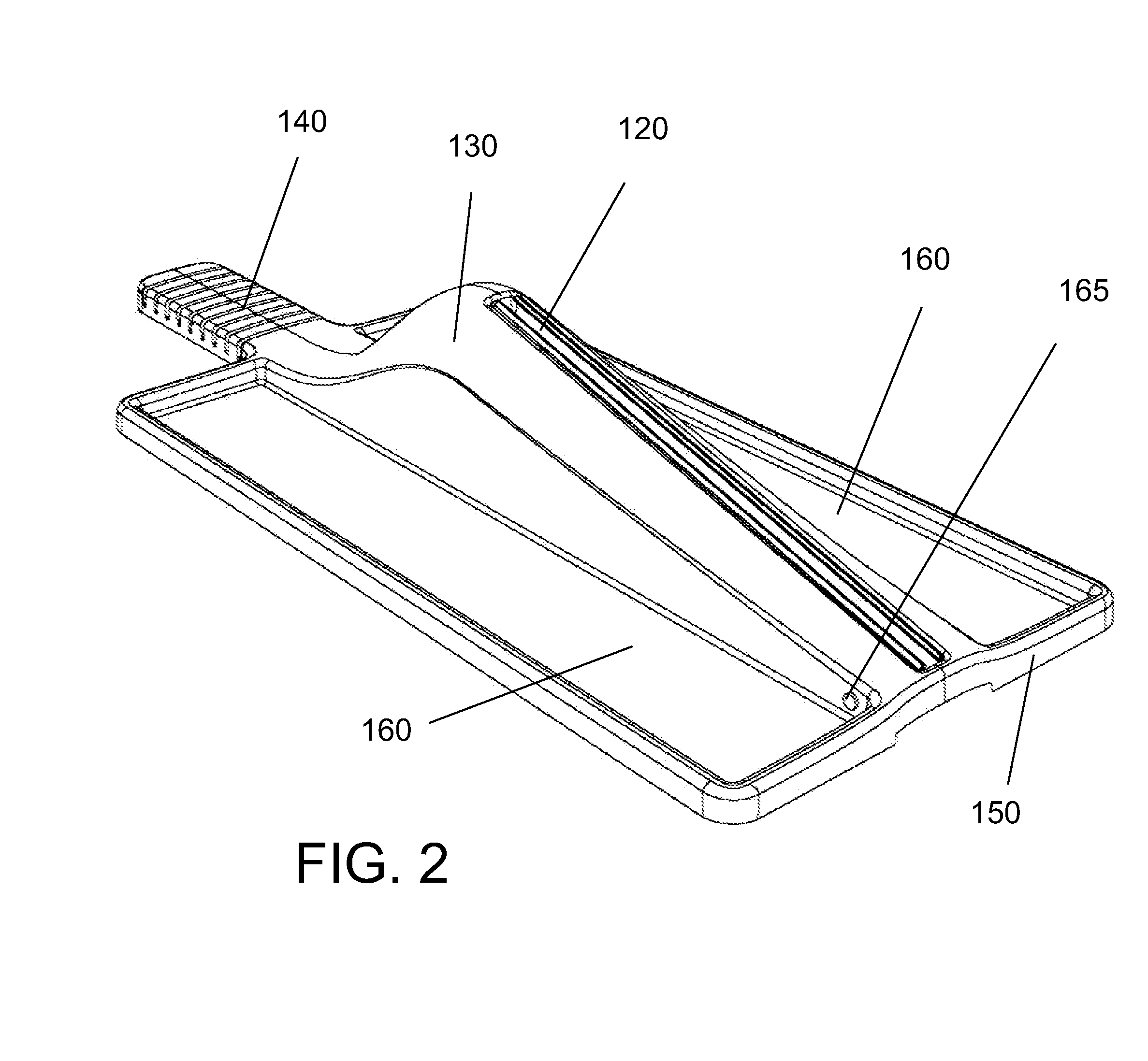
[0034]Referring to FIGS. 1, 2 and 3, a modular solar rack support 100 is shown having a base portion 150, a ballast holding portion 160, a strut 140 and a wedge portion 130. A uni-strut track 120 is disposed along the upper surface of wedge portion 130. A plurality of ballasts 110 are placed on ballast holding portion 160 to hold supports 100 down. A bolt 165 is used to secure another support 100 when assembled with multiple rows.

[0035]Support 100 is made of plastic such as high density polyethylene with UV resistant additives to resist solar breakdown. Of course other ...


PUM


Abstract

A modular solar racking system comprises a plurality of modular solar rack supports that interconnect to provide a portable, non-invasive solar electrical generation system. One embodiment comprises a plastic modular solar rack support having a base portion, a ballast holding portion, a strut and a wedge portion. Supports are interconnected by fitting within grooves in the strut. Uni-strut frames are attached to the supports and solar panels are mounted thereon. In another embodiment, the supports comprise a base portion, a ballast holding portion, a forward lifting portion, a rearward lifting portion and a strut. Again, supports are interconnected by fitting within grooves disposed in the strut. The supports are stackable and are installed on-site using a torque wrench. Ballast may be used to hold the supports down. In one embodiment, a membrane is applied to the bottom surface which is used to adhere the support to a surface.

Description

CROSS REFERENCE TO RELATED APPLICATIONS[0001]This application claims priority and herein incorporates by reference U.S. provisional patent application Ser. No. 61 / 154,002, filed Feb. 20, 2009.BACKGROUND OF THE INVENTION[0002]As alternative energy sources become more important to the economic and environmental well being of society, solar energy use will continue to increase. It is becoming more common to see roofs and other structures having solar panels installed to generate electrical energy. In general, these installations require significant rack systems that may be permanent. These kinds of installations can cause exposure problems to the building due to the required structural penetration to secure the solar panels. Additionally, it is difficult to remove if desired.[0003]To solve this problem, some solar systems utilize racking systems that use ballast to secure them rather than permanent installations. Although this helps in removal and minimizing surface penetrations, it is...

Claims


Application Information

Patent Timeline
IPC IPC(8): H01L31/042F16M13/00
CPCF24J2/4638F24J2/5237F24J2/5239F24J2002/0038F24J2002/5279H02S20/24Y02E10/47Y02E10/50F24J2002/5292H02S20/00Y02B10/12F24S25/11F24S25/16F24S40/85F24S2020/10F24S2025/013F24S2025/02Y02B10/10
Inventor ROTHSCHILD, ELIEHUMPHREY, JOHNSCHNAKENBERG, III, GEORGE H.F.
Owner ROTHSCHILD ELIE
Why Eureka
Try Eureka