Pneumatic tire

a pneumatic tire and tire body technology, applied in the field of pneumatic tires, can solve the problems of difficult to achieve a high level of both steering stability performance and stability guarantee on dry road surfaces, and achieve the effects of reducing improving the stability of the steering surface, and ensuring the rigidity of the land portion on the tread surfa

a pneumatic tire and tire body technology, applied in the field of pneumatic tires, can solve the problems of difficult to achieve a high level of both steering stability performance and stability guarantee on dry road surfaces, and achieve the effects of reducing improving the stability of the steering surface, and ensuring the rigidity of the land portion on the tread surfa

US20100212792A1Active Publication Date: 2010-08-26YOKOHAMA RUBBER CO LTD

Image

  • Pneumatic tire
  • Pneumatic tire
  • Pneumatic tire

Examples


examples

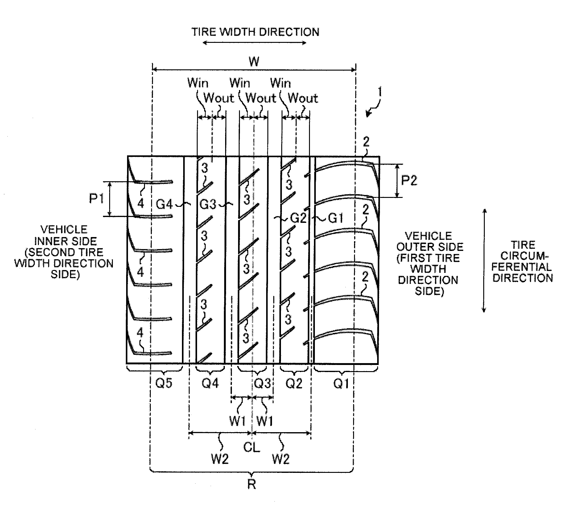
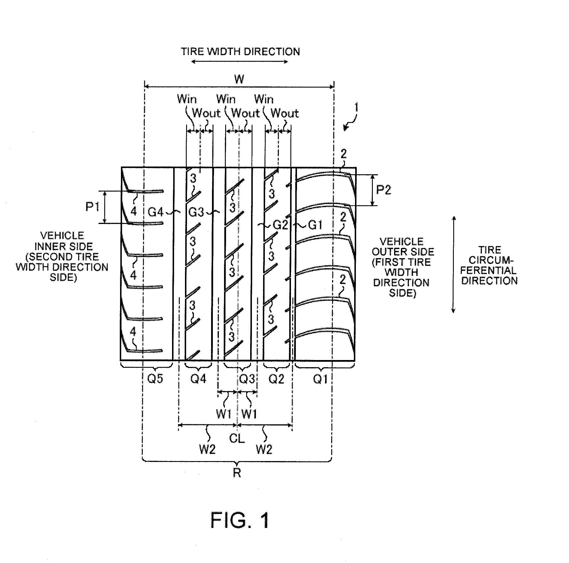
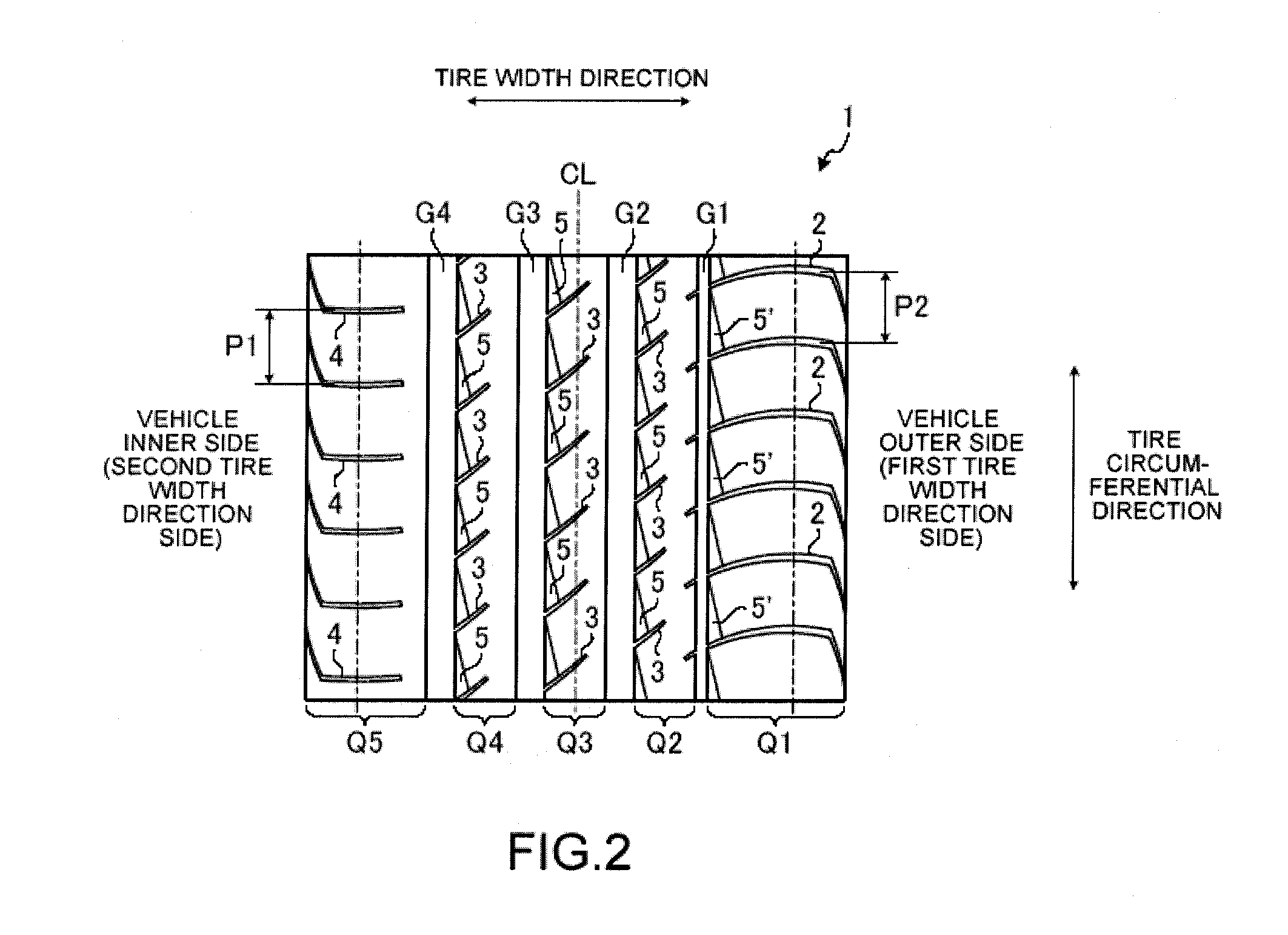
[0044]Using 245 / 40R18 as the tire size and FIG. 1 as the basic form of the tread pattern, the tires of the present invention (Examples 1 to 8) consisting of the pattern configurations shown in FIG. 1 and FIG. 2; a comparative tire (Comparative Example 1) having identical groove widths for main grooves G1, G2, G3, and G4 and having a pattern configuration as shown in FIG. 4 wherein the inclined grooves 3 are connected to the main grooves G1, G2, and G3 and the lug grooves 2 and 4 are not provided; a comparative tire (Comparative Example 2) consisting of a pattern configuration as shown in FIG. 5 having the lug grooves 2 and 4 connected to the main grooves G1 and G4 on both shoulder sides of FIG. 4; a comparative tire (Comparative Example 3) consisting of a pattern configuration as shown in FIG. 6 having the lug grooves 4 of FIG. 1 connected to the main groove G4, and a comparative tire (Comparative Example 4) consisting of a pattern configuration as shown in FIG. 7 equivalent to FIG....


PUM


Abstract

A pneumatic tire including five land portions Q1, Q2, Q3, Q4, Q5 in a tread surface 1 by providing four main grooves G1, G2, G3, and G4 in a ground contact region R of the tread surface 1, wherein positions and groove widths of the main grooves G1, G2, G3, and G4 are specified together with only the land portion Q1 positioned outermost on a vehicle outer side when mounted on a vehicle being formed into a block row, and the other land portions Q2, Q3, Q4, and Q5 being formed into ribs, and a groove area proportion of the tread surface 1 is larger on a vehicle inner side than the vehicle outer side with a tire equator CL and center lines of the land portions Q2, Q3, Q4 as boundaries.

Description

BACKGROUND OF THE INVENTION[0001]1. Field of the Invention[0002]The present invention relates to a pneumatic tire, and more specifically relates to a pneumatic tire that achieves a high level of performance in both steering stability performance on dry road surfaces and steering stability performance on wet road surfaces.[0003]2. Description of the Related Art[0004]In recent years, along with enhanced performance of vehicles, a high level of performance in both steering stability performance on dry road surfaces and steering stability performance on wet road surfaces when driving at high speed has become strongly desired for pneumatic tires.[0005]Guaranteeing drainage by providing many lug grooves and sipes on a tread surface of a tire is normally performed as a method for improving steering stability performance on wet road surfaces. However, there is the problem that it is difficult to guarantee steering stability on dry road surfaces by such a method since a rigidity of land port...

Claims


Application Information

Patent Timeline
26 Aug 2010
Publication
US20100212792A1
IPC
B60C11/03
CPC
B60C11/0306; B60C2011/0381; B60C11/033; B60C11/0304
Inventors
MITA, MASAYA