Valve

a valve and housing technology, applied in the field of valves, can solve the problems of a significant strain state of the closing member-housing combination, and achieve the effect of reducing the strain state of the closing member and avoiding the strain sta

Active Publication Date: 2010-08-26
NELES FINLAND OY
View PDF10 Cites 6 Cited by
  • Summary
  • Abstract
  • Description
  • Claims
  • Application Information

AI Technical Summary

Benefits of technology

[0003]An object of this invention is to solve the above problem and to provide a solution with which a w

Problems solved by technology

However, to achieve a working and easy-to-use valve, this kind of closing member-ho

Method used


Image

  • Valve
  • Valve
  • Valve

Examples


Embodiment Construction

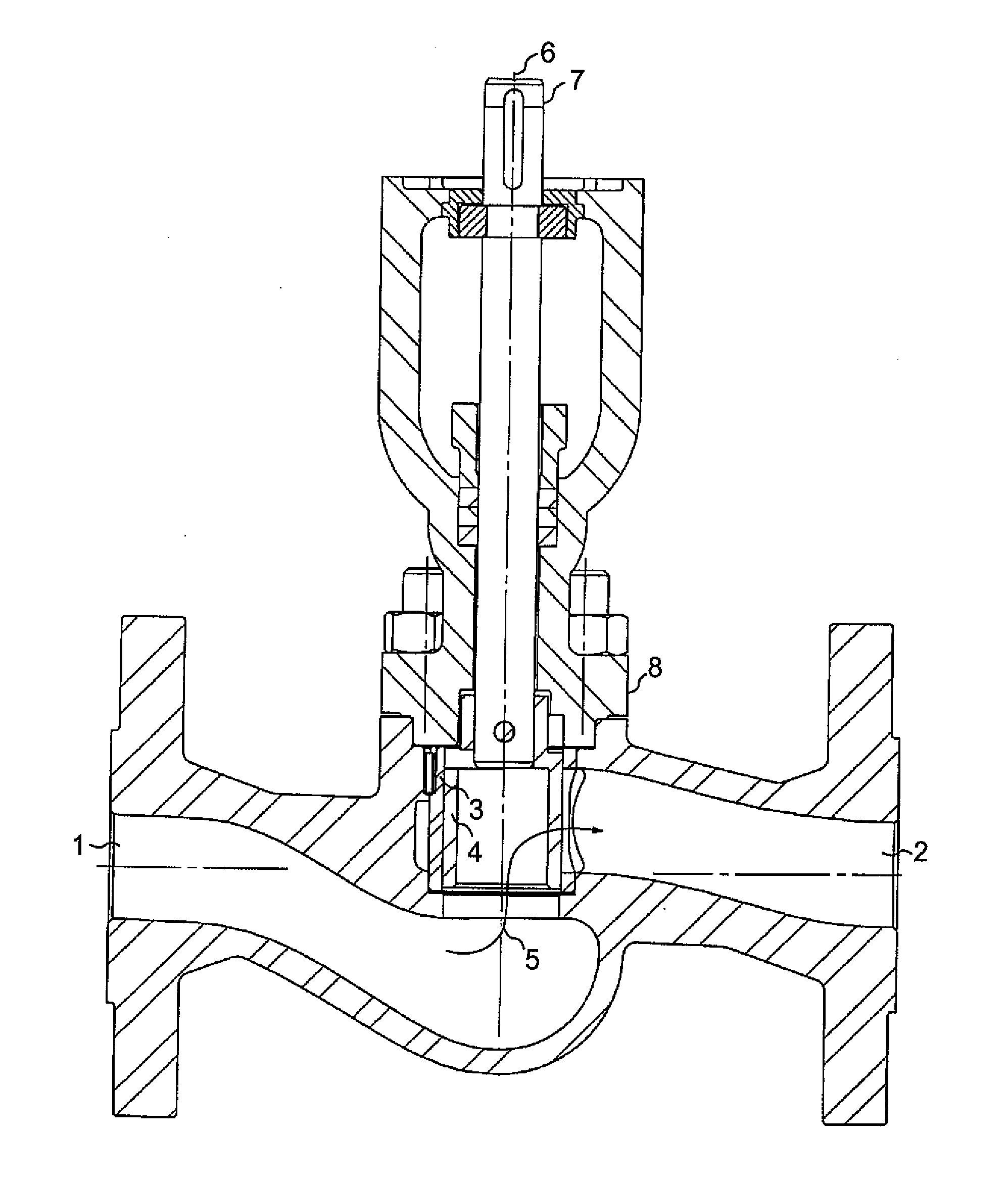
[0010]It is assumed in an exemplary manner that the case of FIG. 1 involves a control valve whose cylindrical housing 3 connects a first part 1 of the flow channel and a second part 2 of the flow channel to each other.

[0011]When a closing member 4 arranged in the housing is in a position allowing flow, the flow takes place in the direction of flow illustrated by arrow 5 from the first part 1 of the flow channel, from the open bottom of the cylindrical housing 3 to the housing, and thereafter through an opening in the wall of the housing 3 to the second part 2 of the flow channel. When the closing member 4 is in a position preventing flow, the closing member 4 is pressed, due to the pressure of a flowing medium, against the wall of the housing 3 and the opening in it. This pressing contributes to the tightness.

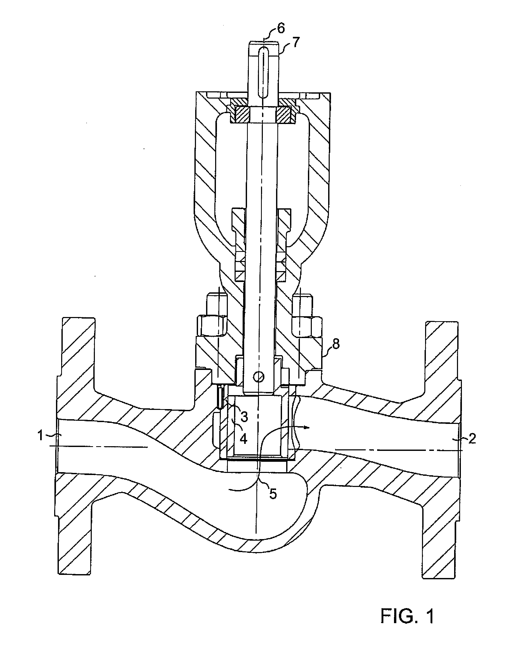
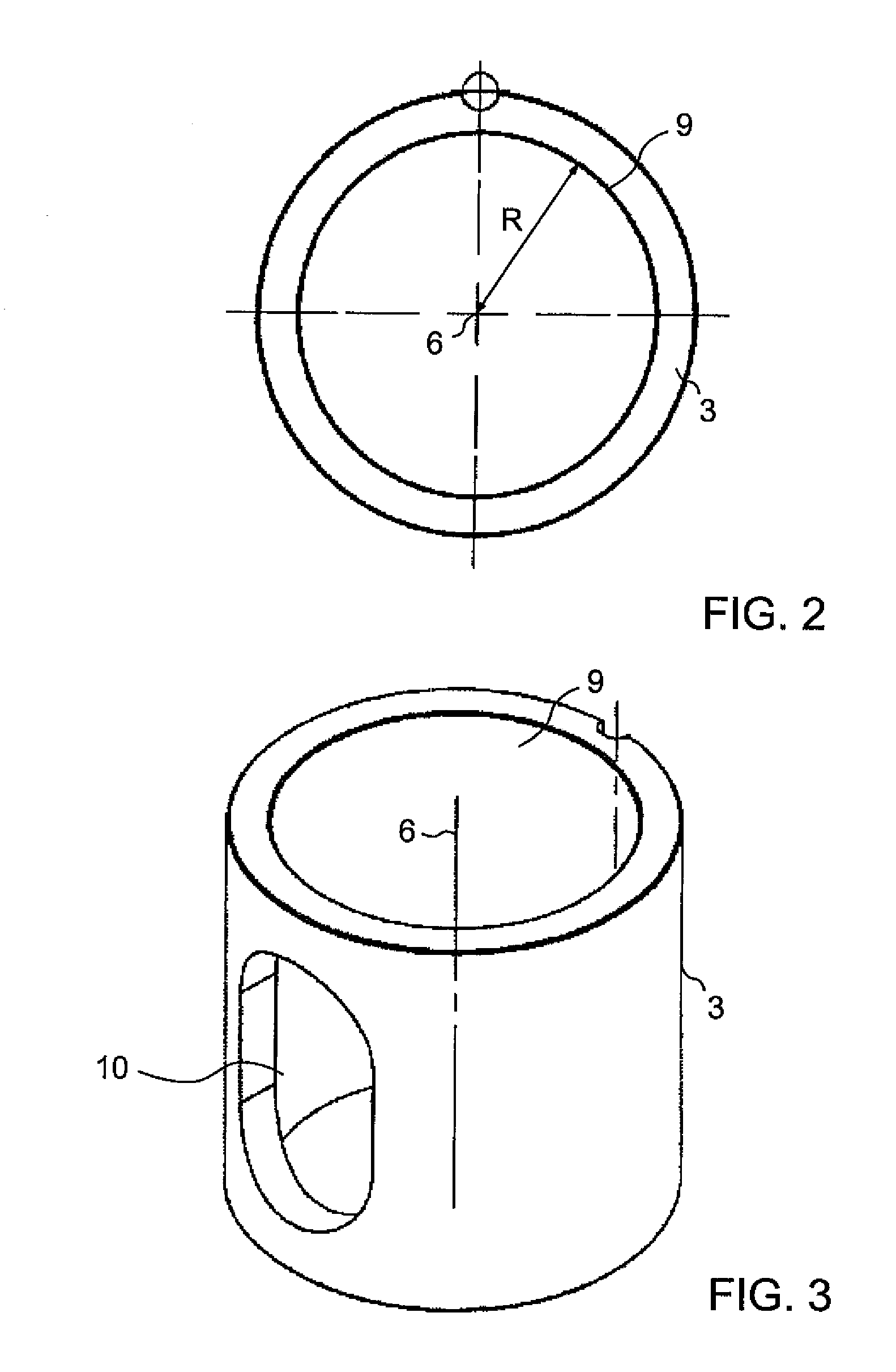
[0012]The closing member 4 arranged in the housing 3 is rotatable around an axis of rotation 6 via a shaft 7 attached to the closing member 4. The shaft 7 is bearing-mounted on...


PUM


Abstract

The invention relates to a valve comprising a housing and a closing member arranged in the housing, from which member a shaft protrudes via which the closing member is rotatable in the housing. In order to provide a working and easy-to-use valve, the closing member comprises a sector closing the opening, a flexible sector having a thinner wall than the closing sector, a guiding sector having the same radius (R) as the inner surface of the housing wall, and an open sector.

Description

FIELD OF THE INVENTION[0001]The present invention relates to a valve, and particularly to a solution providing a working and easy-to-use valve.DESCRIPTION OF PRIOR ART[0002]From the prior art, a valve is known which comprises a cylindrical housing whose wall has an opening for forming a connection between the housing and the flow channel and which is provided with a cylindrically shaped closing member. In this known solution, the cylindrical closing member is dimensioned in such a way that its diameter is greater than the inner diameter of the housing. Thus, when installed in place, the closing member arranged in the housing is pressed against the wall of the housing. However, to achieve a working and easy-to-use valve, this kind of closing member-housing combination that remains in a significant strain state is not a good solution.SUMMARY OF THE INVENTION[0003]An object of this invention is to solve the above problem and to provide a solution with which a working and easy-to-use va...

Claims


Application Information

Patent Timeline
IPC IPC(8): F16K5/04F16K27/06F16K5/18
CPCF16K5/184F16K5/162
Inventor YLI-KOSKI, ESKO
Owner NELES FINLAND OY
Why Eureka
Try Eureka