
Uniformity and stabilizing system for a tire/wheel assembly

a technology of uniformity and stabilizing system, applied in the direction of rotating body balancing, mechanical apparatus, transportation and packaging, etc., can solve the problems of vibration transmission, unsprung mass is susceptible to disturbance and vibration, undesirable or rough vehicle ride,

Inactive Publication Date: 2010-08-26
INT MARKETING
View PDF26 Cites 22 Cited by
  • Summary
  • Abstract
  • Description
  • Claims
  • Application Information

AI Technical Summary

Benefits of technology

[0012]In particular variations, the stabilizing ring is positioned within the tire central portion or within one or both of the tire sidewalls. In other variations, the tire having a stabilizing ring positioned within the central portion by further includes one or more stabilizing rings positoned within one or both of the sidewalls, the one or more additional stabilizing rings being generally completely filled with a flowable weight material, the flowable weight material forming an approximately constant mass around the st

Problems solved by technology

The unsprung mass can be susceptible to disturbances and vibration from a variety of sources such as worn joints, misalignment of the wheel, brake drag, irregular tire wear, etc.
Because vehicular tires support the sprung mass of a vehicle on a road surface and such tires are resilient, any irregularities in the uniformity or dimensions of the tire, any dimensional irregularities in the wheel rim, and / or any dynamic imbalance or misalignment of the tire / wheel assembly will cause disturbances and vibrations to be transmitted to the sprung mass of the vehicle thereby producing an undesirable or rough vehicle ride, as well as reducing handling and stability characteristics of the vehicle.
Severe vibration can result in dangerous conditions such as wheel tramp or hop and wheel shimmy (shaking side-to-side).
However, even perfect balancing of the tire / wheel assembly does not necessarily mean that the tire will roll smoothly.
Even a perfectly balanced tire can have severe vibrations due to non-uniformities in the tire which result in unequal forces within the tire footprint.
A level of non-uniformity is inherent in all tires.
When non-uniformities are of sufficient magnitude, they will cause force variations on a surface, such as a road, against which the tires roll and thereby produce vibrational and acoustical disturbances in the vehicle upon which the tires are mounted.
Regardless of the cause of the force variations, when such variations exceed the acceptable minimum level, the ride of a vehicle utilizing such tires will be adversely affected.
It is unrealistic to believe or expect that all of the tires that do not meet the radial force limitations of the vehicle will not find their way onto a vehicle.

Method used


Image

  • Uniformity and stabilizing system for a tire/wheel assembly
  • Uniformity and stabilizing system for a tire/wheel assembly
  • Uniformity and stabilizing system for a tire/wheel assembly

Examples


Embodiment Construction

[0047]This invention will now be described in detail with reference to various embodiments thereof. The first embodiments relate to the balance weight cartridge of earlier related parent applications. The stabilizing ring, which is the focus of the present application, may be used in conjunction with the cartridge balance weights in at least one embodiment of the invention. In other embodiments, a stabilizing is built into a wheel or a tire.

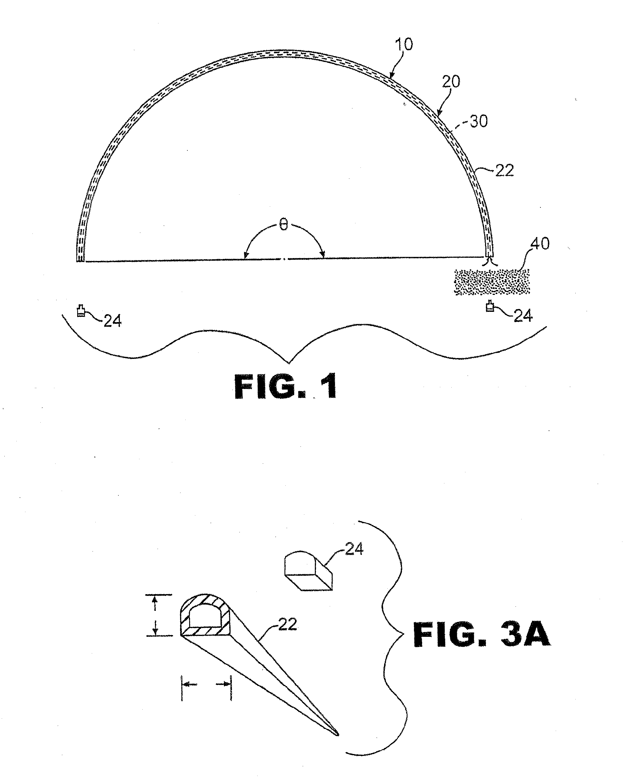
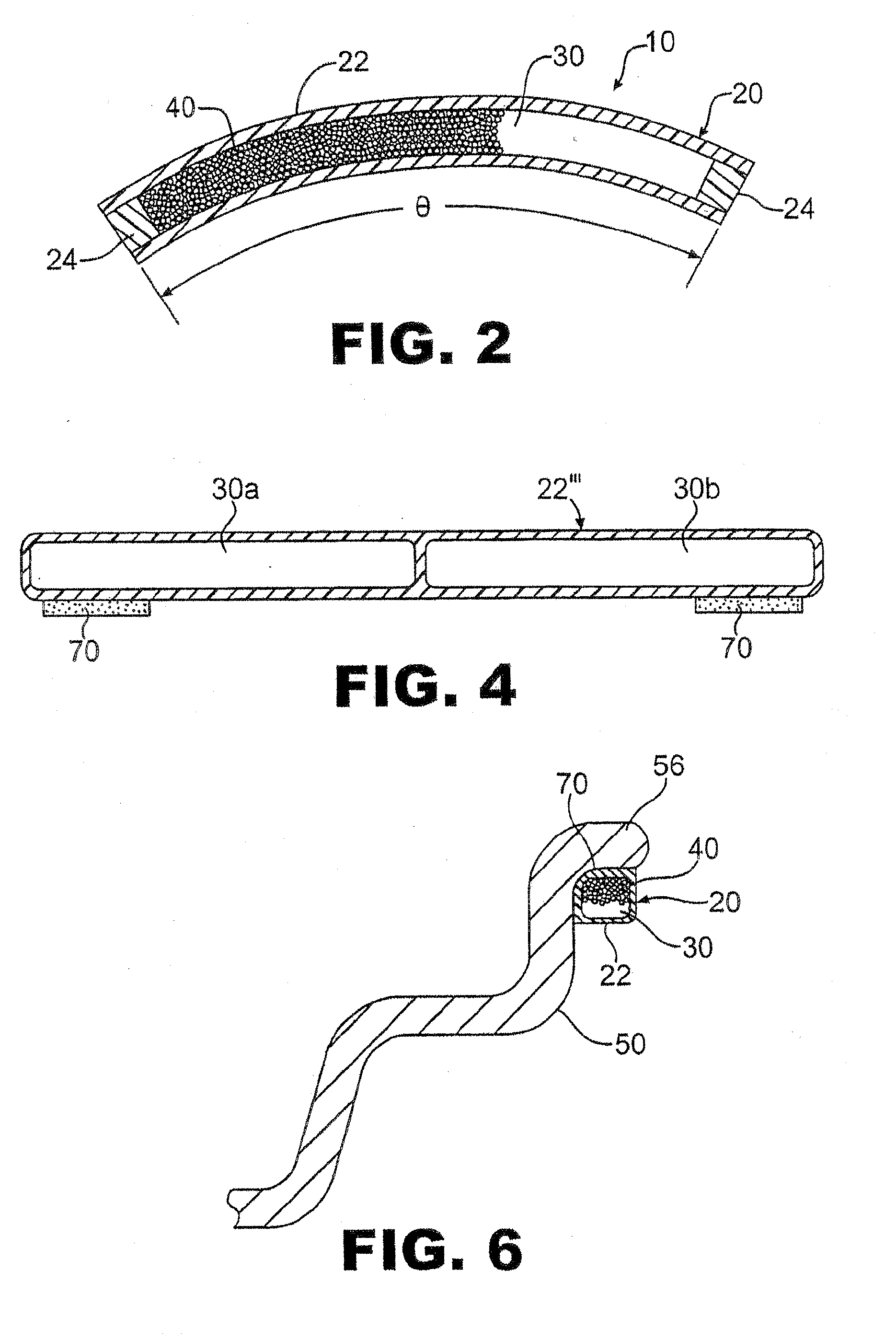
[0048]Referring now to FIGS. 1 and 2, an exploded view and an assembled cross-sectional view, respectively, a balance weight 10 is shown comprising a hollow body or cartridge 20 having a interior chamber 30 at least partially filled with a flowable media 40.The cartridge 20 forms a container and is typically made of a molded or extruded rubber or plastic material that will not react with the metallic surface of a wheel, however the cartridge 20 is not intended to be limited to such materials and any suitable material such as a fabricated aluminum...


PUM


Abstract

Particular embodiments of the present invention include a wheel having a uniformity and stabilizing system. The wheel generally includes a tube well extending axially along a rotational axis of the wheel between axial ends of the wheel, a flange extending from each axial end of the wheel, and a spider portion extending radially inward from an inner side of the tube well. Particular embodiments of the wheel include an annular stabilizing ring formed within the wheel and being generally substantially filled with a flowable weight material to form an approximately constant mass around the stabilizing ring. In other embodiments, the invention comprises a tire having an integrated uniformity and stabilizing system. The tire generally includes a central portion having a tread extending laterally between axial ends and a pair of sidewalls each extending radially inward from one of the axial ends of the central portion. Particular embodiments of the tire include an annular stabilizing ring containing a flowable weight material, the flowable weight material forming an approximately constant mass around the stabilizing ring.

Description

[0001]This application is a continuation-in-part of U.S. non-provisional patent application Ser. No. 11 / 626,145, filed Jan. 23, 2007, now pending, which both claims the benefit of U.S. provisional patent application Ser. No. 60 / 766,560, filed Jan. 27, 2006, hereby incorporated by reference, and is a continuation-in-part of U.S. non-provisional patent application Ser. No. 11 / 559,604, filed Nov. 14, 2006, now abandoned, which is a continuation-in-part of U.S. non-provisional patent application Ser. No. 11 / 276,867, filed Mar. 17, 2006, now U.S. Pat. No. 7,134,731, issued Nov. 14, 2006, which is a continuation-in-part of U.S. non-provisional patent application Ser. No. 11 / 306,397, filed Dec. 27, 2005, now U.S. Pat. No. 7,192,096, which is a continuation of U.S. non-provisional patent application Ser. No. 10 / 806,671, filed Mar. 23, 2004, now U.S. Pat. No. 6,979,060, issued Dec. 27, 2005, which claims the benefit of U.S. provisional patent application Ser. No. 60 / 488,634, filed Jul. 18, 2...

Claims


Application Information

Patent Timeline
IPC IPC(8): B60B19/00F16F15/20B60C19/00
CPCF16F15/366F16F15/324
Inventor FOGAL, SR., ROBERT D.FOGAL, JR., ROBERT D.
Owner INT MARKETING
Features
  • Generate Ideas
  • Intellectual Property
  • Life Sciences
  • Materials
  • Tech Scout
  • Unparalleled Data Quality
  • Higher Quality Content
  • 60% Fewer Hallucinations
Learn More