System and method for automatic determination of the physical location of data center equipment

a data center and automatic discovery technology, applied in the field of data center management, can solve the problems of difficult real-time visualization and monitoring of the date center

Active Publication Date: 2010-08-26
SUNBIRD SOFTWARE INC
View PDF77 Cites 53 Cited by
  • Summary
  • Abstract
  • Description
  • Claims
  • Application Information

AI Technical Summary

Benefits of technology

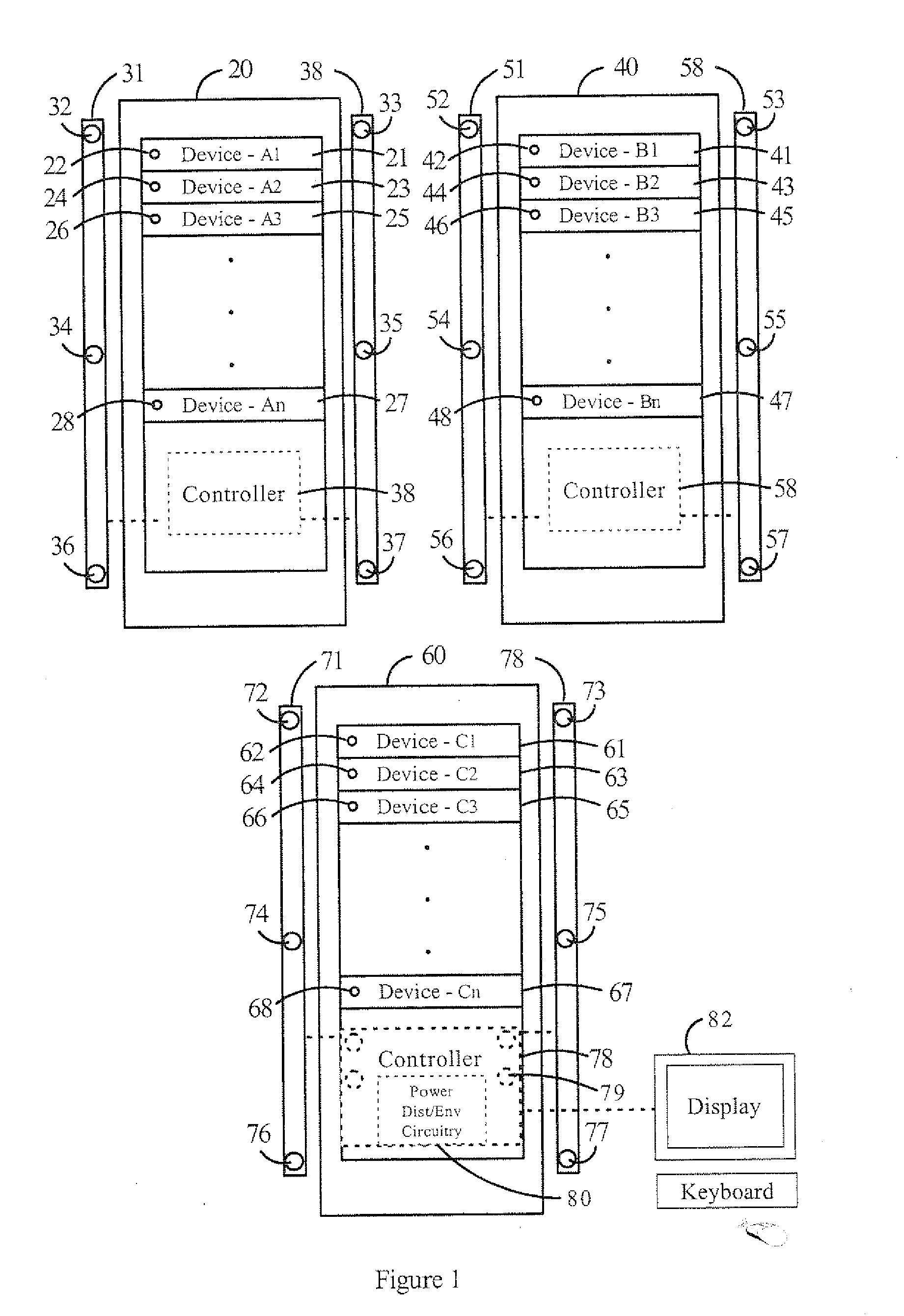
[0009]The map can includes not only relative locations but also the data decoded from an encoded ultrasonic signal (e.g., device serial number, device model number, device status and the like). The system can optionally include one or more supplemental transducers tied to at least one landmark in the data center. The map can also include the relative location of each supplemental transducer. The map can also be formatted with absolute locations of each device. The absolute locations can be derived from the relative locations of each device in cases where the absolute location of at least one landmark in the data center is known.

Problems solved by technology

The manual nature of traditional data center configuration monitoring makes real time visualization and monitoring of the date center extremely difficult.

Method used


Image

  • System and method for automatic determination of the physical location of data center equipment
  • System and method for automatic determination of the physical location of data center equipment
  • System and method for automatic determination of the physical location of data center equipment

Examples


Embodiment Construction

[0020]The invention is directed to systems and methods for automatic discovery of the physical location of data center equipment. It is to be understood that the figures and descriptions of the present invention have been simplified to illustrate elements that are relevant for a clear understanding of the present invention, while eliminating, for the purposes of clarity, many other elements found in typical systems and methods. Those of ordinary skill in the art will recognize that other elements may be desirable and / or required in order to implement the present invention. However, because such elements are well known in the art, and because they do not facilitate a better understanding of the present invention, a discussion of such elements is not provided herein.

I. System Overview

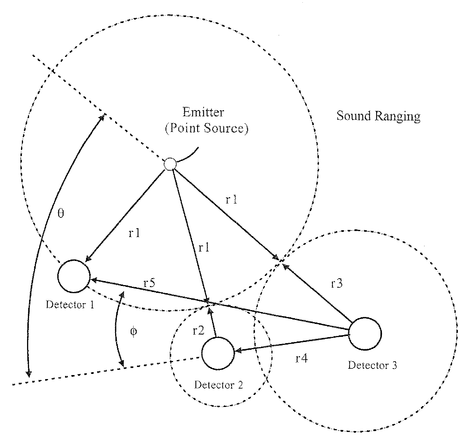
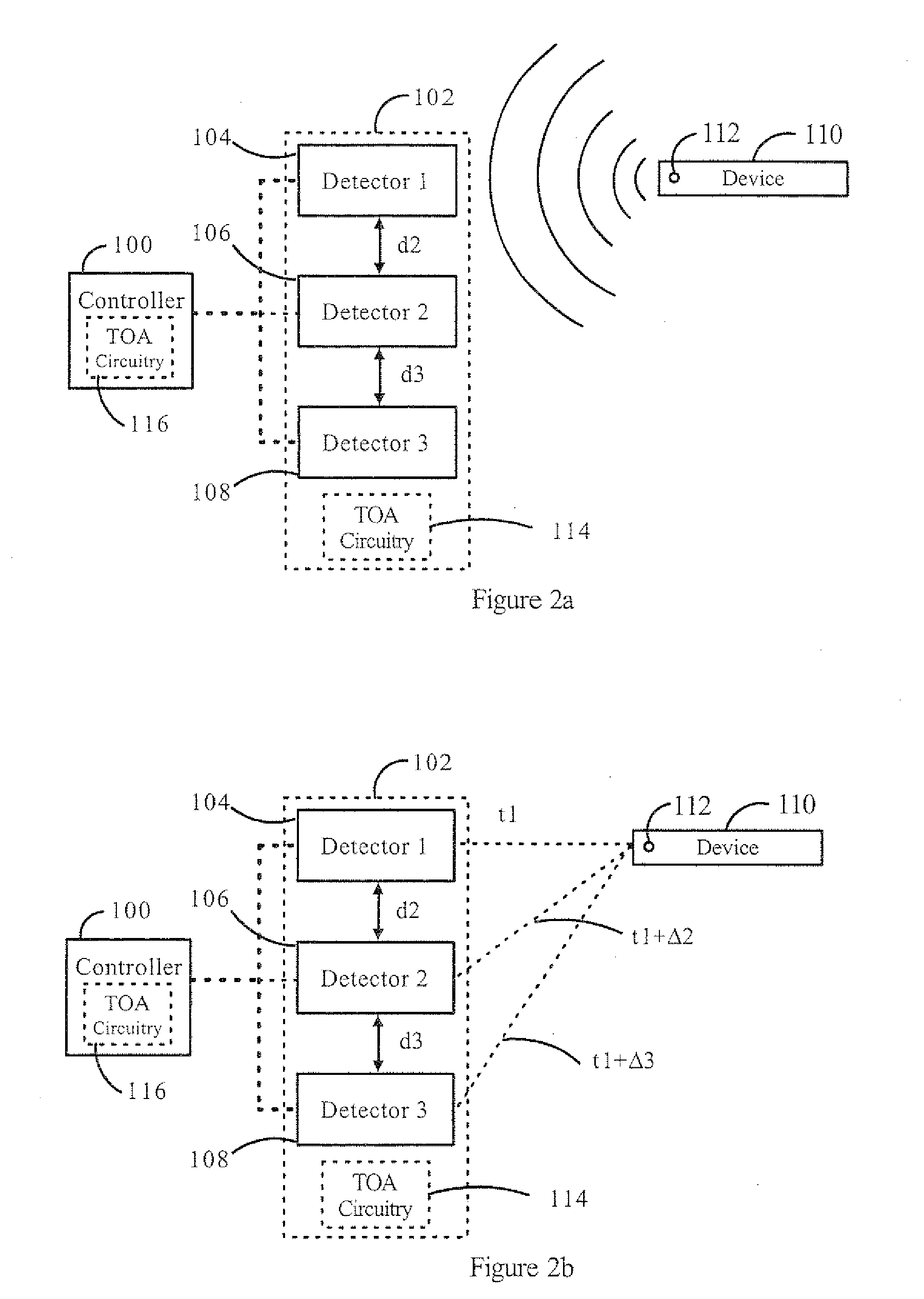
[0021]The invention is directed to systems and methods for automatic discovery of the location of data center equipment. The physical location of data center equipment is determined by utilizing ultrasoun...


PUM


Abstract

The invention is directed to a system and method for automatic discovery of the physical location of at least one device in a data center, the device having an associated ultrasonic emitter. The system generally includes a plurality of ultrasonic detectors having known locations in the data center. A controller initiates the generation of an ultrasonic signal from an ultrasonic emitter associated with a device under test. Time of arrival circuitry generates time of arrival information associated with each ultrasonic detector based on the time of receipt of the ultrasonic signal. The controller determines the location of the device under test based on the known location of the ultrasonic detectors within the data center and the time of arrival information associated with each ultrasonic detector.

Description

CROSS-REFERENCED TO RELATED APPLICATIONS[0001]This application claims priority from Provisional Patent Application No. 61 / 106,900 filed Oct. 20, 2008. This application also is related to U.S. patent application Ser. No. 12 / 112,435, entitled, “System and Method for Efficient Association of a Power Outlet and Device,” filed on Apr. 30, 2008, and to U.S. patent application Ser. No. 12 / 168,504, entitled, “Automatic Discovery Of Physical Connectivity Between Power Outlets And It Equipment”, filed on Jul. 7, 2008, both of which are assigned to the same assignee, and which are incorporated herein by reference in their entireties.FIELD OF THE INVENTION[0002]The invention relates generally to the field of data center management and more specifically to systems and methods for automatic discovery of the physical location of data center equipment.BACKGROUND OF THE INVENTION[0003]Modern data centers and IT infrastructures undergo frequent changes due to routine maintenance, upgrades and the lik...

Claims


Application Information

Patent Timeline
Patent Type & Authority Applications(United States)
IPC IPC(8): G01S15/06
CPCH05K7/1498G01S5/22
Inventor SOMASUNDARAM, SIVAMALIK, NAIM R.WANG, BRIAN
Owner SUNBIRD SOFTWARE INC
Why Eureka
Try Eureka