
Method for Determining Dense Disparity Fields in Stereo Vision

Active Publication Date: 2010-08-26
TELECOM ITALIA SPA
View PDF6 Cites 7 Cited by
  • Summary
  • Abstract
  • Description
  • Claims
  • Application Information

AI Technical Summary

Benefits of technology

[0022]According to another possible alternative, the first and the second image can comprise at least one version with lower resolution and a version with greater resolution; in that case the step of determining the previous displacement component comprises minimising the optical flow objective function for the version with lower resolution, and determining the residual displacement component comprises minimising the optical flow objective function for the version with greater resolution.

Problems solved by technology

The Applicant observed that the techniques described in previously cited documents do have problems, even though the introduction of constraints imposed by epipolar geometry in the optical flow technique allows improving the computation of disparity fields between two images.
In particular, such techniques constrain the solution of the optical flow equations to lie on the epipolar line.
Such an imposition, in case of errors in computing the epipolar lines, typically due to camera calibration inaccuracies, makes the computed solution not optimal with respect to the shot scene.

Method used


Image

  • Method for Determining Dense Disparity Fields in Stereo Vision
  • Method for Determining Dense Disparity Fields in Stereo Vision
  • Method for Determining Dense Disparity Fields in Stereo Vision

Examples


Embodiment Construction

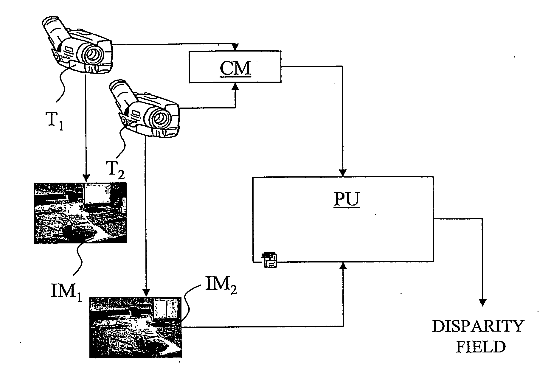
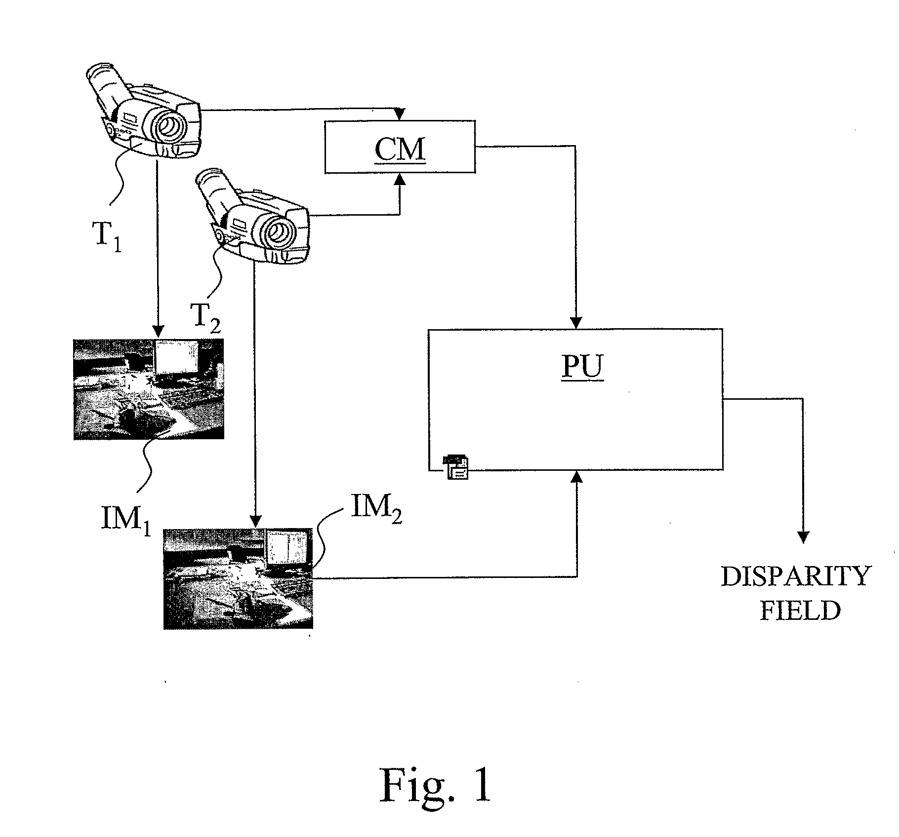
[0030]With reference to FIG. 1, S denotes, as a whole, a video capture system with several cameras. In particular, the system S is adapted for shooting from different positions of a same scene and for determining dense disparity fields between the images thereby acquired.

[0031]The system S comprises a first camera T1 and a second camera T2 / adapted to generate respective digital images (or frames) IM1, IM2 of a same scene. The two cameras T1, T2 may be oriented towards the scene as mutually parallel or mutually inclined.

[0032]The system S further comprises a processing unit PU, connected to both cameras T1, T2, and adapted to process digital images IM1 and IM2 received from the two cameras T1, T2 in order to obtain a dense disparity field according to the method described below. Moreover, the system comprises a camera calibration module CM, preferably a software module being present in the processing unit PU, or in a separate unit (as in the example of FIG. 1), adapted to provide the...


PUM


Abstract

In a stereo vision system comprising two cameras shooting the same scene from different positions, a method is performed for determining dense disparity fields between digital images shot by the two cameras, including the steps of capturing a first and a second image of the scene, and determining, for each pixel of the second image, the displacement from a point in the first image to such pixel of the second image minimising an optical flow objective function, wherein the optical flow objective function includes, for each pixel of the second image, a term depending in a monotonously increasing way on the distance between the epipolar line associated with such pixel and the above point in the first image, such term depending on calibration parameters of the two cameras and being weighed depending on the uncertainty of the calibration data.

Description

TECHNICAL FIELD[0001]The present invention deals, in general, with a method for automatically analysing stereo vision images, in particular a method for determining dense disparity fields when the epipolar geometry is known.[0002]A frequent problem to be solved when automatically analysing images is determining the disparity that describes the difference existing between two frames showing the same scene, acquired from different points of view with one or more cameras. The disparity represents the difference in position of the same scene element in the two frames. There are algorithms which compute the disparity for every image pixel, and there are other ones which are limited to a subset thereof, namely to a group of relevant features. In the former case, these are called dense disparity fields, in the latter case these are called sparse disparity fields. The present invention pertains to the first category.[0003]A known technique for comparing two images and determining the corres...

Claims


Application Information

Patent Timeline
IPC IPC(8): G06K9/00G06V10/147
CPCG06K9/209H04N13/0246G06T7/0022G06T7/97H04N13/246H04N2013/0081G06V10/147
Inventor FRANCINI, GIANLUCACORDARA, GIOVANNILEPSOY, SKJALG
Owner TELECOM ITALIA SPA
Learn More