Blower impeller and blower

a technology of blower and impeller, which is applied in the direction of non-positive displacement fluid engines, pump components, reaction engines, etc., can solve the problems of impeller cup breakage, impeller cup breakage, and difficulty in simply increasing the wall thickness, so as to improve the strength of the cup portion, excellent retention, and the effect of improving strength

Inactive Publication Date: 2010-08-26
NIDEC CORP
View PDF12 Cites 36 Cited by
  • Summary
  • Abstract
  • Description
  • Claims
  • Application Information

AI Technical Summary

Benefits of technology

[0014]An impeller according to this preferred embodiment is excellent in retaining a rotor holder and has an improved strength, because the rotor holder arranged inside the cup portion can be retained by the first ribs, and the strength of the cup portion is reinforced by the second ribs. That is, the first ribs are arranged to perform a primary function of retaining the rotor holder while the second ribs are arranged to perform a primary function of reinforcing the strength of the cup portion.
[0015]The aforementioned effects are accomplished because the second ribs do not provide resistance when the rotor holder is press-fitted to an inside of the cup portion, and the second ribs arranged between the first ribs act to equalize uneven stresses applied to an outer wall portion of the cup portion. Thus, an improvement in the strength of the impeller is achieved while the impeller maintains the capacity of retaining the rotor holder, without increasing the wall thickness of the cup portion or increasing the number of first ribs to retain the rotor holder.

Problems solved by technology

When the rotor holder is press-fitted to the entire inner circumferential surface of the impeller cup, a significantly uneven shape of the rotor holder or the impeller cup leads to an excessive pressure being applied to a portion of the impeller cup, which will result in a breakage of the impeller cup.
This problem becomes evident when the impeller is caused to rotate at a high speed in order to increase the air flow quantity of the blower.
However, it is difficult to simply increase the wall thickness thereof because of a deformation accompanying contraction when the impeller is molded of the resin, a constraint in terms of the outer diameter of the impeller cup 101, and so on.
However, an increase in the number of ribs results in increased resistance when the rotor holder is press-fitted to the impeller cup, which may also lead to the breakage of the impeller cup 101.

Method used


Image

  • Blower impeller and blower
  • Blower impeller and blower
  • Blower impeller and blower

Examples


Embodiment Construction

[0036]Hereinafter, preferred embodiments of the present invention will be described in detail with reference to the accompanying drawings. Note that the present invention is not limited to the preferred embodiments described below, and that variations and modifications can be made as appropriate as long as desired effects of the present invention are not impaired. Also note that the preferred embodiments may be combined with other preferred embodiments.

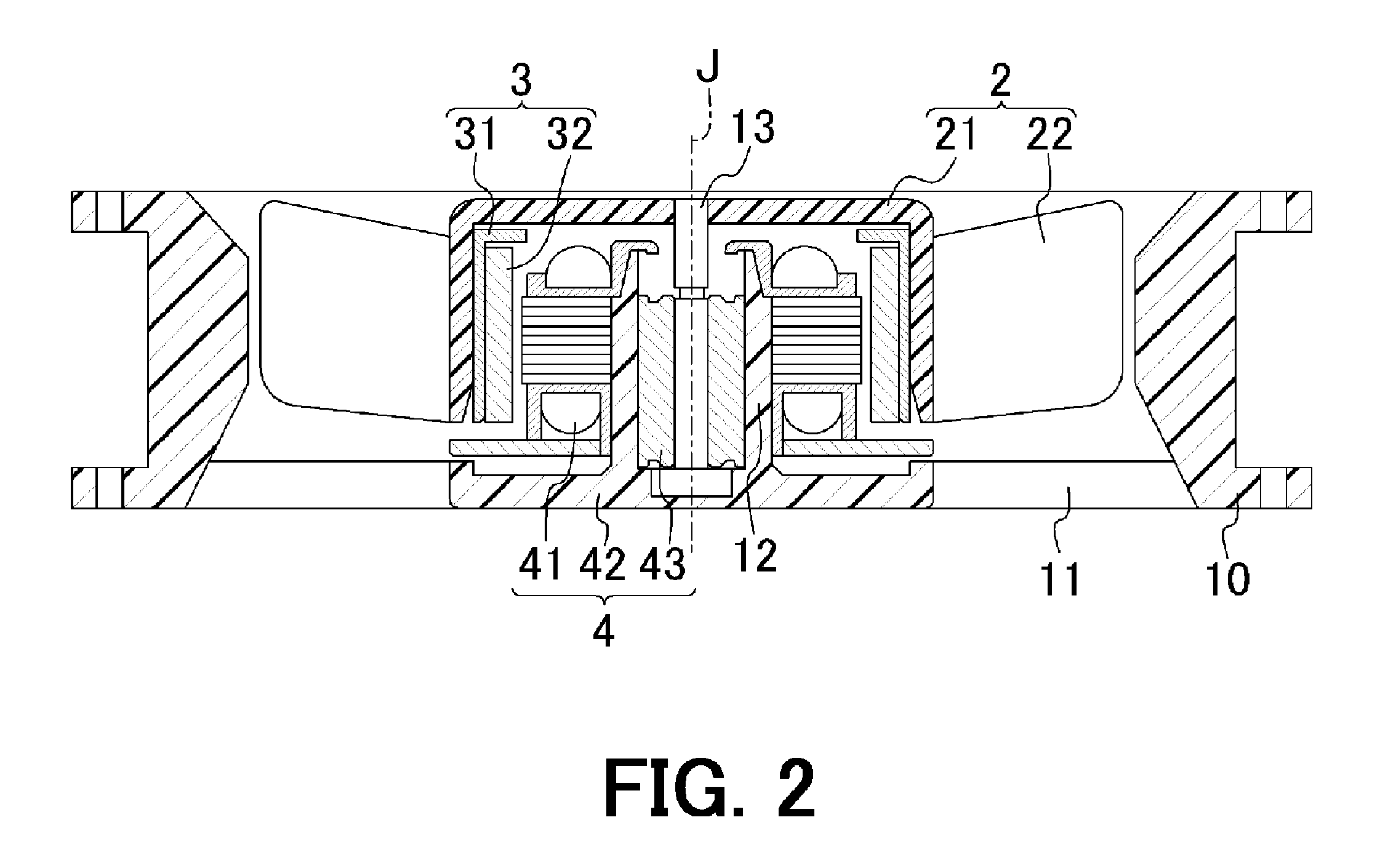
[0037]First, the structure of a blower using a blower impeller according to a preferred embodiment of the present invention will now be described below with reference to FIG. 2.

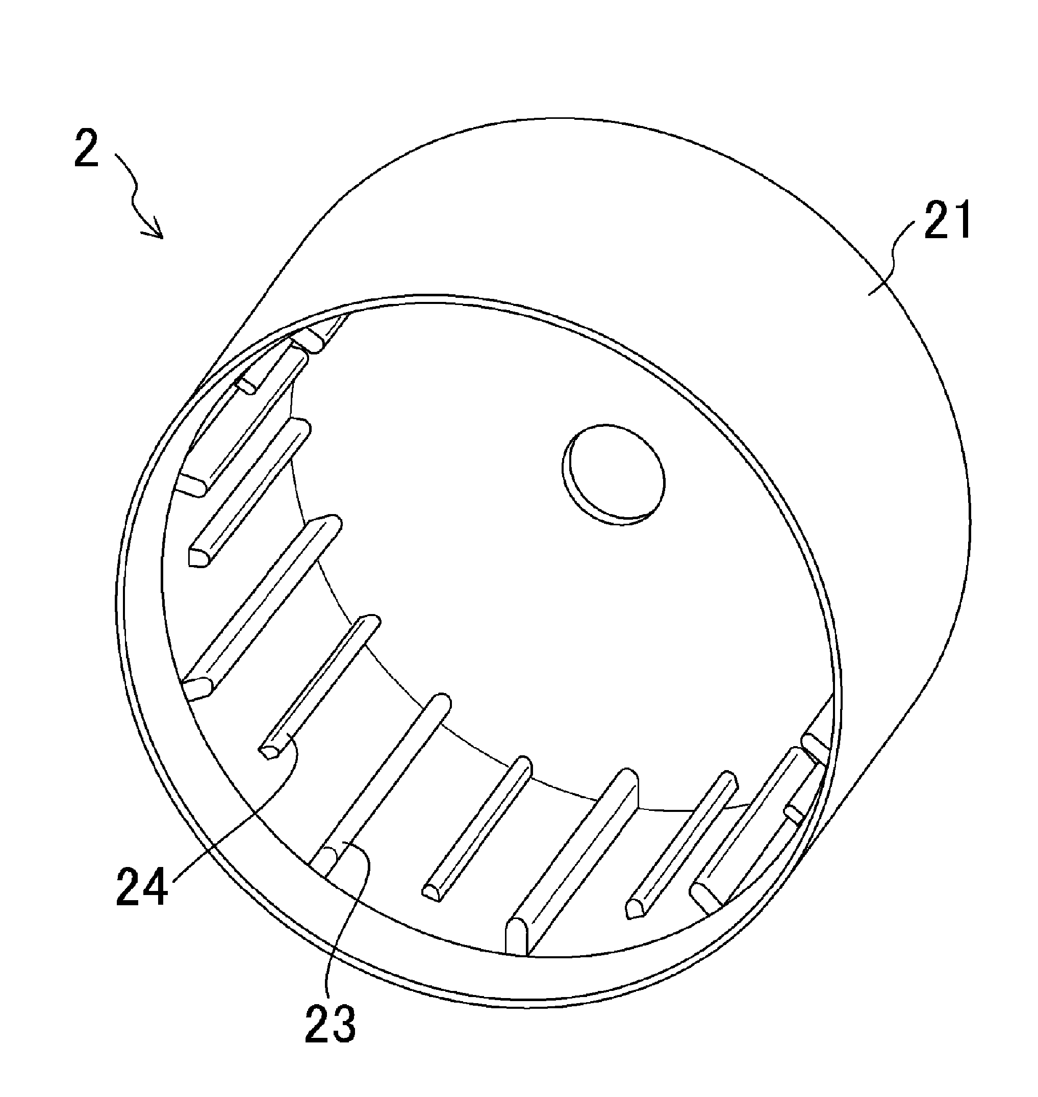
[0038]FIG. 2 is a cross-sectional view of the blower according to a preferred embodiment of the present invention taken along a plane including a central axis J. In FIG. 2, an impeller 2 including a cup portion 21 and a plurality of blades are contained in a housing 10. The cup portion 21 is substantially defined by the shape of a covered cylinder. The blades 2...


PUM


Abstract

A blower impeller includes a substantially cylindrical cup portion, and a plurality of blades arranged on an outer circumferential surface of a circumferential wall portion of the cup portion. The cup portion includes on an inner circumferential surface of the circumferential wall portion thereof a plurality of axially extending first ribs and a plurality of second ribs arranged between the first ribs. The first and second ribs are arranged in a circumferential direction. A virtual envelope joining radially inner end portions of the first ribs has a smaller diameter than that of a virtual envelope joining radially inner end portions of the second ribs.

Description

BACKGROUND OF THE INVENTION[0001]1. Field of the Invention[0002]The present invention relates to the structure of an impeller. More specifically, the present invention relates to an impeller for use in a blower.[0003]2. Description of the Related Art[0004]In conventional blowers (blower fans), a motor is arranged inside a cylindrical impeller cup to rotate an impeller with a plurality of blades. The motor includes a stator portion and a rotor portion supported so as to be rotatable with respect to the stator portion. A cylindrical rotor holder is press-fitted to an inner circumferential surface of the impeller cup, so that the impeller is fixed to the rotor holder.[0005]When the rotor holder is press-fitted to the entire inner circumferential surface of the impeller cup, a significantly uneven shape of the rotor holder or the impeller cup leads to an excessive pressure being applied to a portion of the impeller cup, which will result in a breakage of the impeller cup.[0006]JP-A 2008...

Claims


Application Information

Patent Timeline
Patent Type & Authority Applications(United States)
IPC IPC(8): F04D29/38F04D29/26
CPCF04D25/0613F04D29/662F04D29/329
Inventor TAKESHITA, HIDENOBU
Owner NIDEC CORP
Why Eureka
Try Eureka