Air operated double diaphragm over center valve pump

a technology of air-operated and center valve pumps, which is applied in the direction of pumping, positive displacement liquid engines, machines/engines, etc., can solve the problems of increasing the cost and complexity of the pump, and achieve the effects of reducing time and cost, sacrificing performance or longevity, and reducing cos

Inactive Publication Date: 2010-08-26
WARREN RUPP INC
View PDF23 Cites 18 Cited by
  • Summary
  • Abstract
  • Description
  • Claims
  • Application Information

AI Technical Summary

Benefits of technology

[0063]One advantage of this invention is the cost reduced design allows for a competitive advantage within the marketplace without sacrificing performance or longevity.
[0064]Another ad

Problems solved by technology

Conventional valve systems/arrangements utilize a high number of parts, some of whi

Method used


Image

  • Air operated double diaphragm over center valve pump
  • Air operated double diaphragm over center valve pump
  • Air operated double diaphragm over center valve pump

Examples


Embodiment Construction

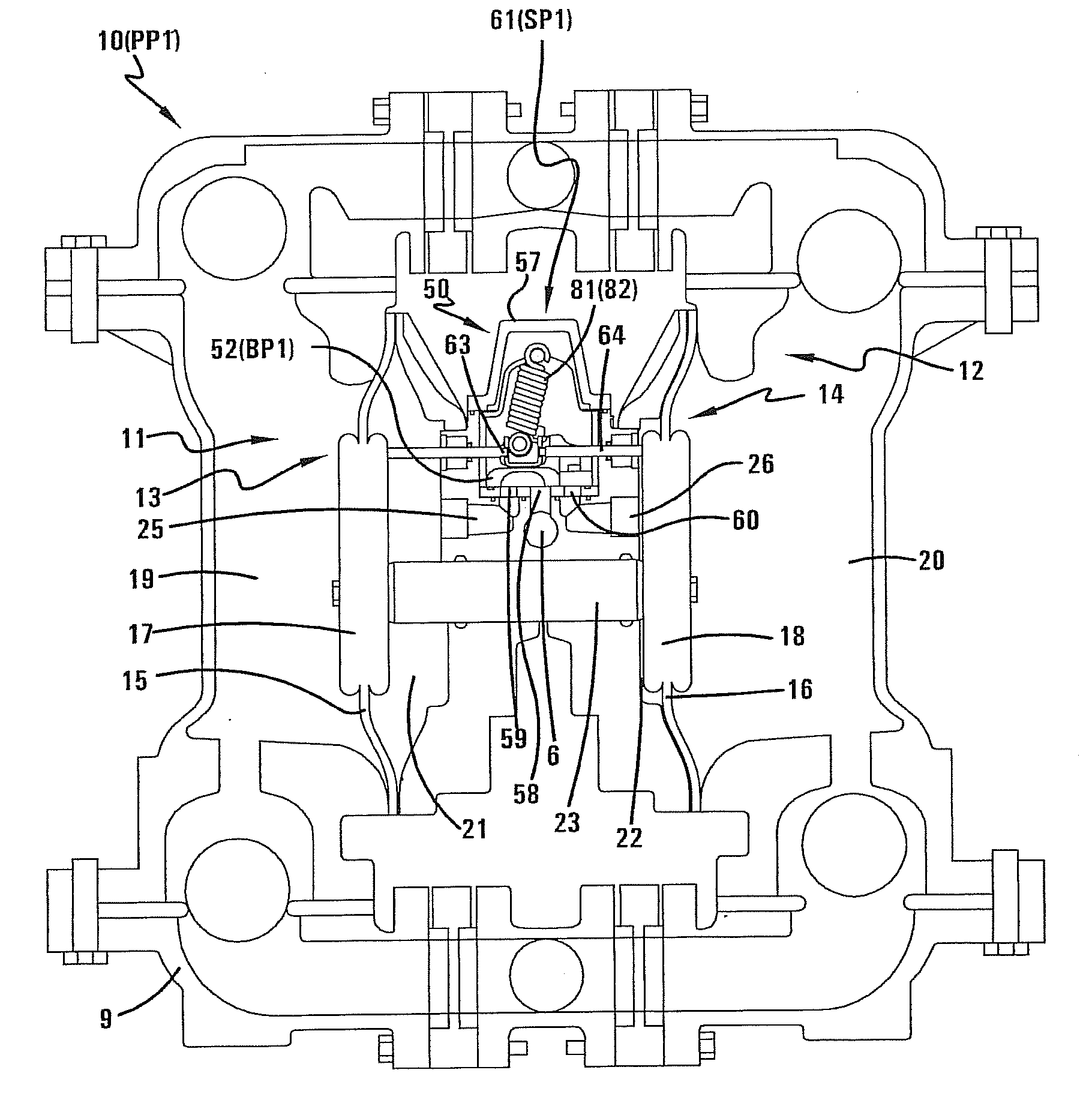
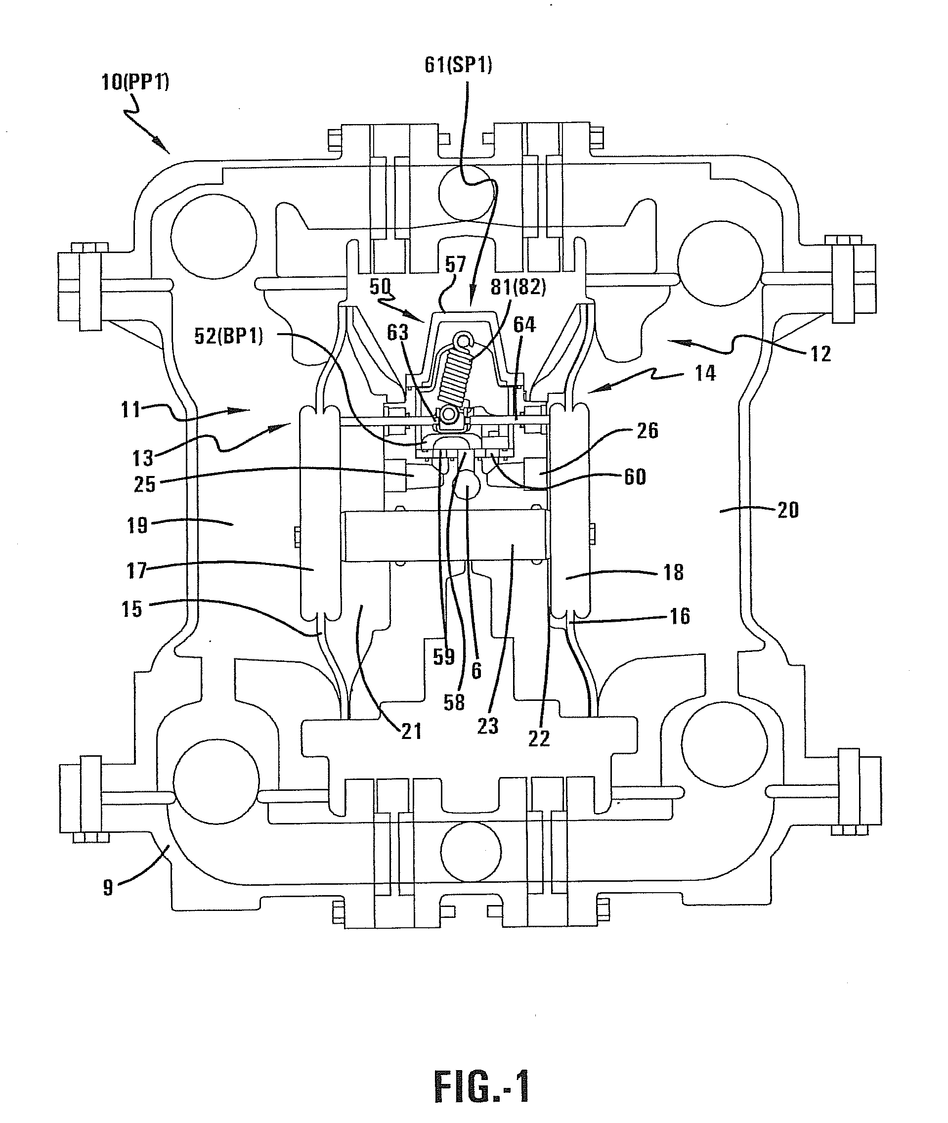
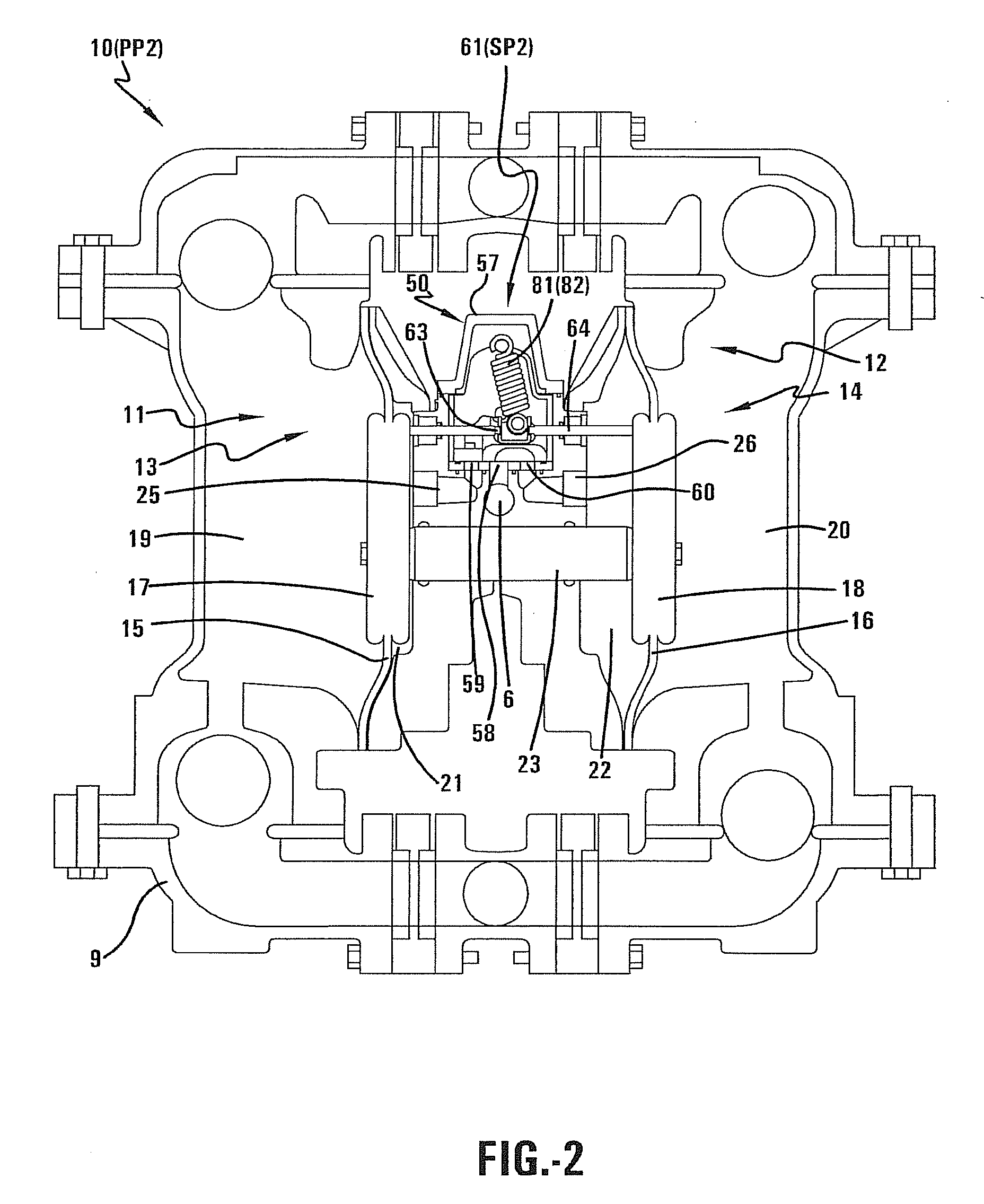
[0074]Referring now to the drawings wherein the showings are for purposes of illustrating embodiments of the invention only and not for purposes of limiting the same, FIG. 1 shows an air operated double diaphragm pump 10 comprising an air valve mechanism 50 according to one embodiment of the invention. The air valve mechanism 50 may comprise a single valve system that replaces the two valve system found in conventional air operated double diaphragm pumps. The position of the valve may be determined by the diaphragm motion of the pump up to a stall position. A spring-loaded mechanical actuation may complete the valve action from the stall position to the final or end of stroke position of the pump. While the air valve mechanism 50 may be advantageously used for various purposes, the air valve mechanism 50 will be described below in connection with an air actuated diaphragm pump apparatus having reciprocating diaphragms for pumping liquid such as, for example, solutions, viscous mater...


PUM


Abstract

An air operated double diaphragm pump comprising an air valve mechanism. The air valve mechanism may comprise a single valve system that replaces the two valve system found in conventional air operated double diaphragm pumps. The position of the valve may be determined by the diaphragm motion of the pump up to a stall position. A spring-loaded mechanical actuation may complete the valve action from the stall position to the final or end of stroke position of the pump.

Description

I. BACKGROUND[0001]A. Field of Invention[0002]This invention pertains to the art of methods and apparatuses regarding air operated double diaphragm pumps.[0003]B. Description of the Related Art[0004]Conventional air operated double diaphragm (AODD) pumps utilize a two valve system to enable alternating air action between the pumps double diaphragms. Typically, the two valve system includes a pilot valve and a main spool valve. The motion of the pump's diaphragm assemblies causes the main spool valve to alternate between two positions in order to cause compressed air to be alternately drawn into and exhausted from the two fluid chambers of the pump as the two diaphragm assemblies reciprocate between a first and a second position. The movement of the main spool valve cannot rely solely on the motion of the diaphragms since the diaphragm motion would only push the valve to a center or stall position where both chambers are blocked off and unable to either draw in or exhaust out compres...

Claims


Application Information

Patent Timeline
IPC IPC(8): F04B45/033F04B45/02F16K31/44
CPCF01L7/06F04B43/0736F01L2003/25F01L23/00
Inventor KREBS, LARRY FRANCISSUNADA, CRAIG DANIELCONNELL, MARK EDWARD
Owner WARREN RUPP INC
Why Eureka
Try Eureka