
Electronic system for tracking and monitoring articles to be sterilized and associated method

a technology of electronic system and article, applied in the direction of electromagnetic radiation sensing, chemical methods analysis, instruments, etc., can solve the problems of multiplicity, inability to read prior to the detection of fluorescence by the auto reader, and inability to detect fluorescence of commercially available sterilization indicators found in packs, etc., to reduce the hold time of sterile products, avoid delay, cost and inaccuracy, and acquire, store and use.

Inactive Publication Date: 2010-08-26
3M INNOVATIVE PROPERTIES CO
View PDF98 Cites 13 Cited by
  • Summary
  • Abstract
  • Description
  • Claims
  • Application Information

AI Technical Summary

Benefits of technology

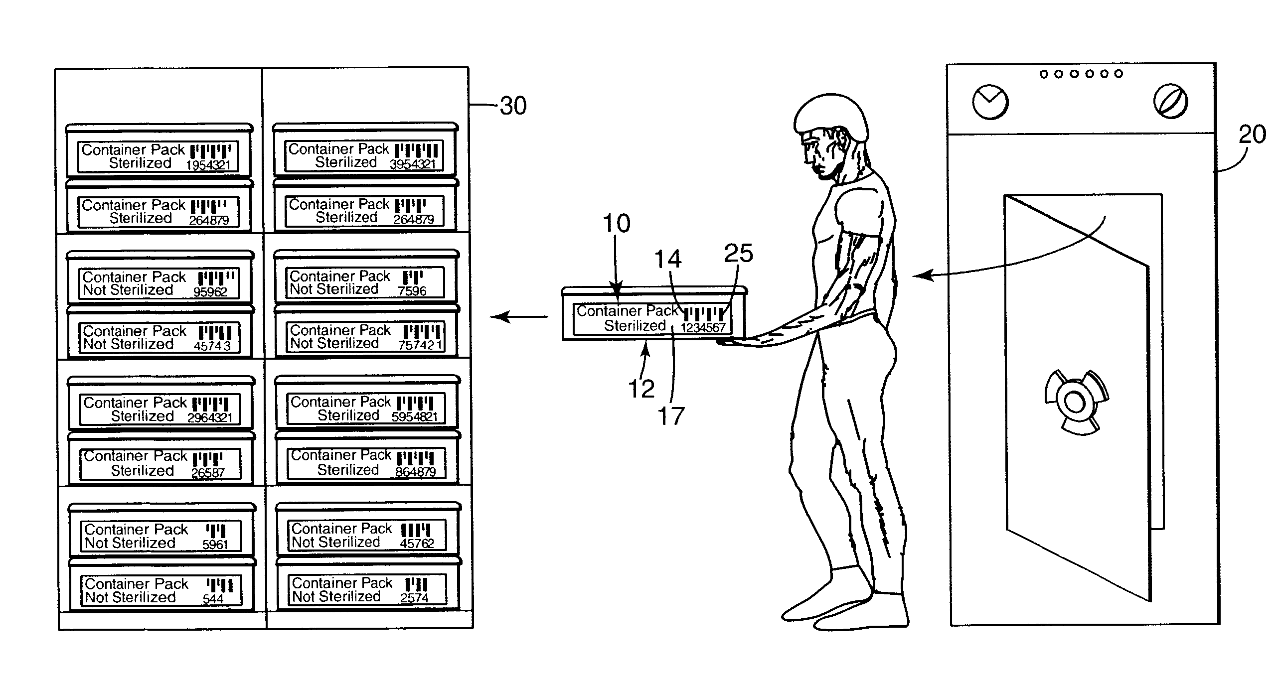
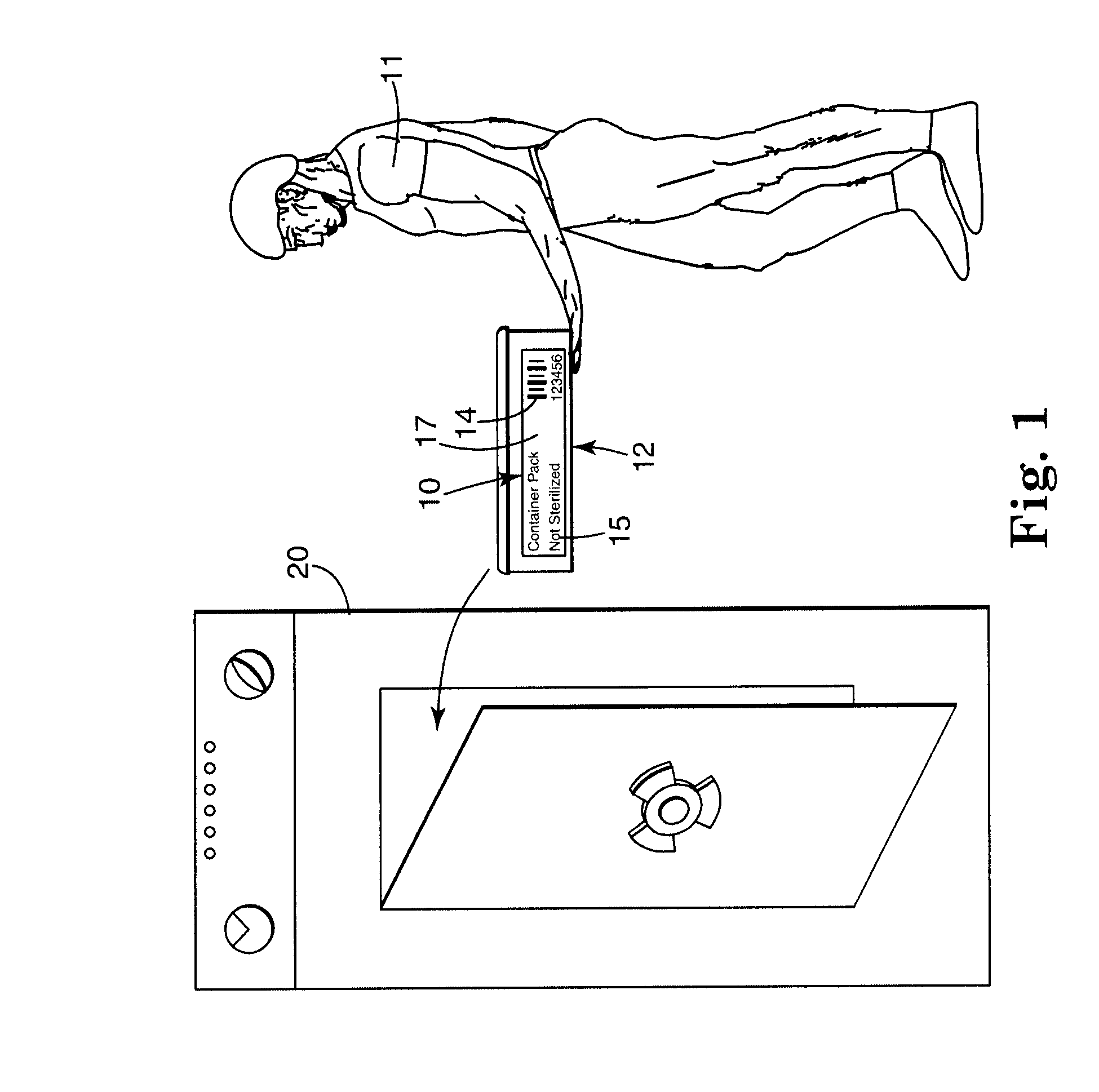
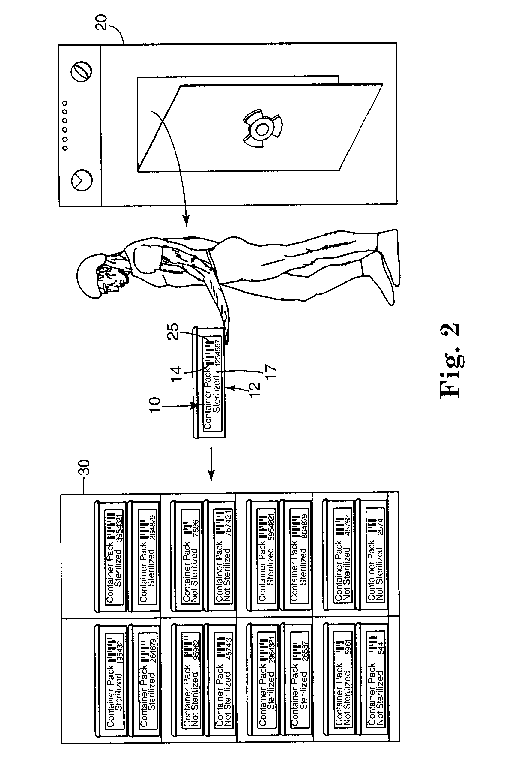
[0023]The present invention comprises a sterilization indicator and monitoring method that affords the user the ability to: a) acquire, store and use sterilization monitoring information quickly and cost effectively without the delay, cost and inaccuracy associated with prior art sterilization indicators, b) reduce sterile products inventory hold time, increase the accuracy of information storage and provide higher levels of accuracy in data management, c) possess a unified, integrated sterility assurance and inventory management system, d) minimize the potential for human error in a system for monitoring the sterilization of articles, and e) customize sterilization assurance information for site specific needs.

Problems solved by technology

This is challenging, as objects can be contaminated with any of a number of different types of bacteria, some more dangerous and tougher to kill than others.
If the steam sterilization cycle was lethal, the auto reader will not detect fluorescence within a predetermined time.
However, commercially available sterilization indicators found within packs cannot be read prior to opening the pack because sterilization wrap is typically opaque.
If the sterilization indicator inside a pack indicates a failed sterilization cycle, there are many problems in finding out about it just prior to use of the items within the pack.
The problems are multiplied when the sterilization indicator identifying a failure is found within the specially prepared and maintained sterile field.
Some users find it difficult to subjectively determine whether a chemical indicator has changed color.
This is particularly a problem for a user who suffers from color blindness.
For example, some persons who suffer from color blindness have difficulty distinguishing red colors from green colors.
This color change may be difficult for some users to distinguish with the attendant risk of inaccurate recordation of sterilization information.
The contrast between these particular colors is difficult for some users to perceive.
Biological indicators suffer from some of the same problems as chemical indicators.
There are many ways that human error can adversely affect a hospital's sterilization assurance procedures.
Because sterilization indicators are small, they can simply become lost, especially if their use entails transportation between different hospital functions, locations or departments.
When a hospital utilizes several different types of sterilizers (e.g. steam sterilizers, flash steam sterilizers, ethylene oxide sterilizers or vapor phase hydrogen peroxide sterilizers), it makes the recording problem even more complex.
To address the problems mentioned above, hospitals invest in significant and costly training of personnel responsible for sterilization monitoring.
However, these require manual steps associated with the sterilization information tracking.
The prior art inventory management systems require the user to manually input a great deal of data relating to these different types of sterilization indicators with the attendant risk that the user will improperly record the information or fail to record it at all.
The difficulty associated with accurately recording sterilization information is exacerbated by the fact that chemical indicator information is typically recorded just after a sterilization cycle while biological indicator information is recorded many hours or days after the sterilization cycle.
Prusik et al. does not disclose a chemical indicator for use in monitoring a sterilization procedure at a health care facility.
Moreover, users do not have the ability to generate their own indicators.
There is little chance for customization of the indicator at the hospital.

Method used


Image

  • Electronic system for tracking and monitoring articles to be sterilized and associated method
  • Electronic system for tracking and monitoring articles to be sterilized and associated method
  • Electronic system for tracking and monitoring articles to be sterilized and associated method

Examples


example 1

[0184]Eight gallons of white steam indicator ink were triple roller milled using the composition described in Table 1a. The ink was screen printed on Monatec 5111-120 paper available from Monadnock Paper Mills, Bennington, Vt. The printed paper was cut to form indicator strips (Run 1) 20.3 centimeters long and 1.6 centimeters wide (8 inches by ⅝ inch) and perforated in the middle. The strips were overcoated using a 390 mesh screen with “UV #600” ultraviolet protector available from Midwest Coatings, Inc., North Kansas City, Mo. The amount of ink deposited after drying was 0.008 grams / square centimeter. Sheets were also screen printed with white steam indicator ink on Type S-14526 paper available from Kimberly Clark, Atlanta, Ga. However the sheets were not overcoated (Run 2).

TABLE 1aWhite Steam Indicator Ink Formulation used in Runs 1-2ComponentGenericWeightNameTrade Name / Source / Address(percent)LeadHalstab White Lead A / Halstab / Hammond, IN24.88carbonateSulfur#21-95 / Akronchem / Akron, O...

example 2

[0190]An indicating composition for use in a hydrogen peroxide sterilization procedure was prepared by combining the elements of the formulation listed in Table 2a.

TABLE 2aHydrogen Peroxide indicator Ink Formulation used in Run 1ComponentGenericWeightNameName / Source / Address(percent)Acid FuschinSigma-Aldrich Fine Chemicals / St. Louis, Mo.0.18Sodium SaltRhoplexRohm & Haas Corp. / Philadelphia, PA36.30I-545ShellacMantrose Bradshaw Zinsser Group / Westport,18.20BleachedCTBone DryEthyl18.20AlcoholIsopropylExxon Chemical Corp. / Houston, TX27.22Alcohol

[0191]The ink formulation was gravure flood coated onto S&S 410 Grade Filter Paper from Schleicher & Schuell Corp., Keene, N. H. Code 39 bar codes B were modified as described in Example 1. Ten Modified Code Bs were sterilized in a Sterrad 100 from Advanced Sterilization Products (ASP) full cycle and scanned as described in Example 1. The results are shown in Table 2b.

TABLE 2bScanning ResultsNumber Read / RunHueNumber ScannedNumberInkBeforeAfterBefor...

example 3

[0193]U.S. Pat. Nos. 4,731,222; 4,892,706; 5,037,623; 5,077,008; and 5,091,343 (the entire contents of each of which are herein incorporated by reference) describe liquid peracetic acid sterilization procedures for which the present invention may be employed.

[0194]Indicator strips available from Steris Corp., Mentor, Ohio were used to monitor a sterilization process including the use of a liquid peracidic acid solution (e.g. the STERIS SYSTEM 1™ AND Steris 20™ Sterilant Concentrate available from Steris Corp.). The ninth bar of Code B was replaced with strips cut from the indicator strips before and after sterilization in the Steris System 1™ Full Processing Cycle. The Modified Code Bs were scanned as described in Example 1. The results are shown in Table 3a.

TABLE 3aScanning ResultsNumber Read / RunHueNumber ScannedNumberInkBeforeAfterBeforeAfterStandard20 / 20Code B1CommercialDark PurplePale Blue 0 / 109 / 10Indicator Strips(Steris)

[0195]An incorrect scan angle can give false results.


PUM

PropertyMeasurementUnit
incidence angleaaaaaaaaaa
illumination incidence angleaaaaaaaaaa
concentrationaaaaaaaaaa

Abstract

An electronic system for tracking and monitoring articles to be subjected to a sterilization cycle is disclosed. The method uses a sterilization indicator and electronically links sterilization information with the articles subjected to the sterilization process. The indicator allows a sterilization cycle to be monitored without the need for a user to subjectively distinguish between color, quality or intensity of display patterns.

Description

CROSS-REFERENCE TO RELATED APPLICATIONS[0001]This application is a continuation of U.S. application Ser. No. 11 / 472,671, filed Jun. 22, 2006, which is a divisional of U.S. application Ser. No. 10 / 303,465, filed Nov. 25, 2002, which is a continuation of U.S. application Ser. No. 09 / 369,098, filed Aug. 5, 1999, which issued as U.S. Pat. No. 6,485,979 on Nov. 26, 2002, which are incorporated herein by reference.FIELD[0002]This invention relates to sterilization indicators, sterilization information and methods of monitoring articles to be sterilized. The present invention relates particularly to a sterilization indicator that can be machine read to provide a user with information relating to a sterilization process. With the present invention, information relating to the efficacy of a sterilization cycle can be machine read and / or electronically linked to integrated electronic information systems throughout the health care provider system.BACKGROUND[0003]Sterilization is the act of kil...

Claims


Application Information

Patent Timeline
Patent Type & Authority Applications(United States)
IPC IPC(8): G06Q10/00G06Q50/00G06K7/10A61L2/26A61L2/28G16H40/20
CPCA61L2/24A61L2/28A61L2202/14Y10T436/102499G06Q50/22G06F19/327Y10T436/15A61L2202/24G16H40/20
Inventor KIPPENHAN, ROLAND C.KIRCKOF, STEVEN S.BOLEA, PHILIP A.RUMBLE, RICHARD M.HEHENBERGER, RODNEY K.IGNACIO, RAMON T.
Owner 3M INNOVATIVE PROPERTIES CO
Learn More