Vibration resistant fastener

Active Publication Date: 2010-09-02
HANON SYST
View PDF13 Cites 0 Cited by
  • Summary
  • Abstract
  • Description
  • Claims
  • Application Information

AI Technical Summary

Benefits of technology

[0007]Presently provided by the invention, a fastener resistant to vibration that may be installed and removed without the use of special tools, provi

Problems solved by technology

These vibrations pose design challenges to manufacturers.
Fasteners used to assemble various components of the automobile may eventually fail as a result of vibration.
As a result, the fastener may be damaged or the fastener may be destructively removed and replaced.
The automobile and the fasteners used therein

Method used


Image

  • Vibration resistant fastener
  • Vibration resistant fastener
  • Vibration resistant fastener

Examples


Example

[0015]The following detailed description and appended drawings describe and illustrate an embodiment of the invention. The description and drawings serve to enable one skilled in the art to make and use the invention, and are not intended to limit the scope of the invention in any manner.

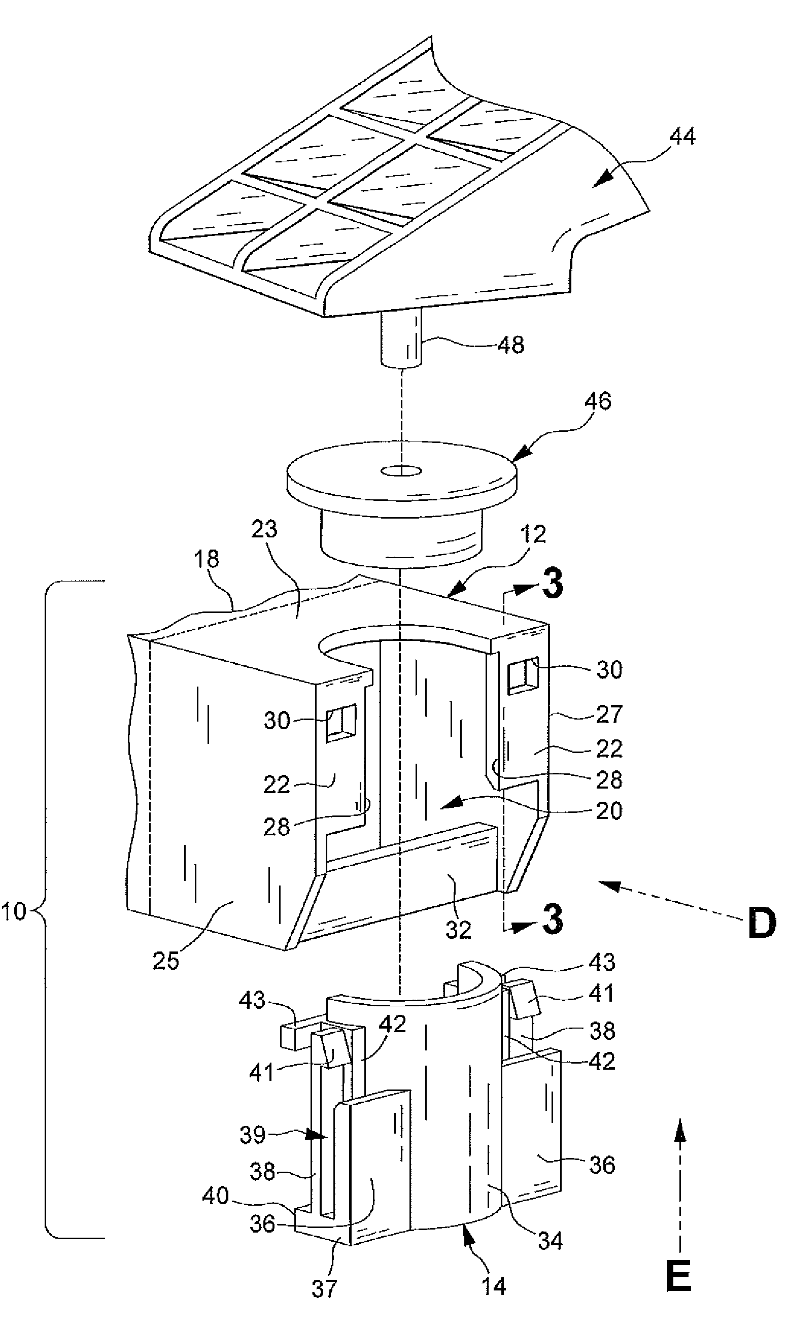
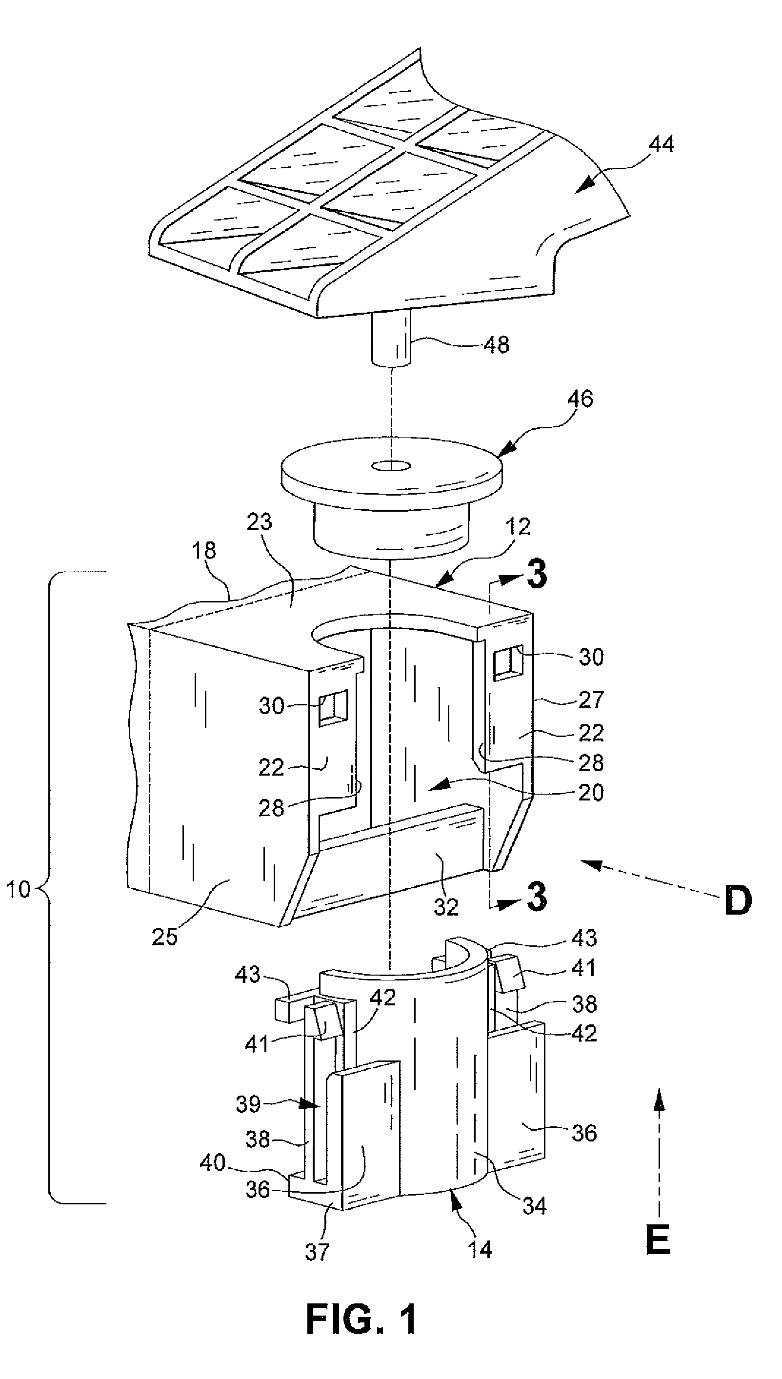
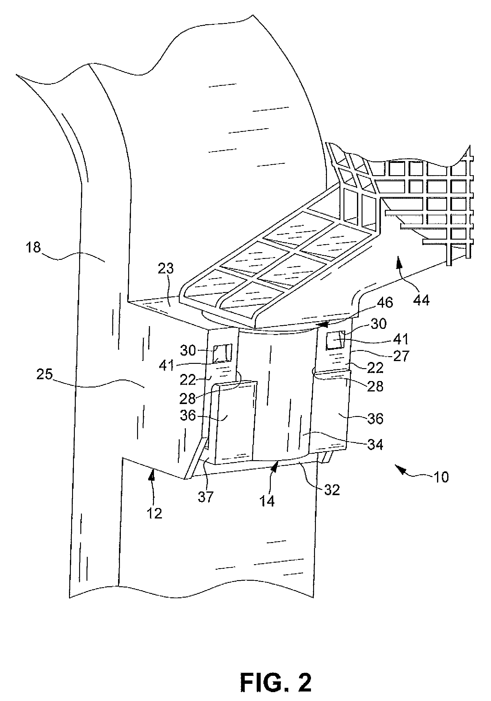
[0016]FIGS. 1-3 illustrate a fastener 10 according to the present invention. The fastener 10 includes a capture body 12 and a retainer clip 14.

[0017]As shown, the capture body 12 is substantially rectangular and is integrally formed with a mounting structure 18. The mounting structure 18 may be disposed in a vehicle or other structure upon which other components are attached. A cavity 20 is formed in the capture body 12. A pair of tabs 22 partially enclose the cavity 20. The tabs 22 extend laterally inwardly from an upper wall 23 and one of a first side wall 25 and a second side wall 27 of the capture body 12. A pair of spaced apart inner edges 28 of the tabs 22 are substantially parallel and form a...


PUM


Abstract

A fastener having a capture body including a cavity formed therein and a retainer clip including an elongate capture support and a pawl for engagement with the capture body. The fastener being resistant to vibration and able to be installed and removed without the use of special tools, while providing consistent fastening through thermal expansion cycles, and supporting assembly “stack-up” tolerances is disclosed.

Description

FIELD OF THE INVENTION[0001]The invention relates to fasteners and more particularly to fasteners resistant to vibrations.BACKGROUND OF THE INVENTION[0002]Automobiles and other machines may vibrate during normal operation. These vibrations pose design challenges to manufacturers. Fasteners used to assemble various components of the automobile may eventually fail as a result of vibration.[0003]Special tools may be required during installation of components of the automobile to install and remove the fasteners. When a required special tool is unavailable, another tool may be used in an attempt to complete the task. As a result, the fastener may be damaged or the fastener may be destructively removed and replaced.[0004]The automobile and the fasteners used therein are also subjected to extreme temperature variations. A range of temperature from about −20° F. to about 120° F. is typical for most of the fasteners used in the automobile. Since components of the automobile are subjected to...

Claims


Application Information

Patent Timeline
IPC IPC(8): F16B2/02F16D1/05
CPCY10T403/41F16B21/065
Inventor KOLLAR, JAN GREGUSSHEPPARD, ERIC NEAL
Owner HANON SYST
Why Eureka
Try Eureka