Mixer Capable of Improving Signal Quality

a mixer and signal technology, applied in the field of mixers, can solve problems such as unsatisfactory transistors of conventional mixers, and achieve the effect of improving signal quality and reducing harmonic interferen

Active Publication Date: 2010-09-02
MEDIATEK INC
View PDF5 Cites 4 Cited by
  • Summary
  • Abstract
  • Description
  • Claims
  • Application Information

AI Technical Summary

Benefits of technology

[0010]In view of the foregoing issues, one object of the present invention is to provide a mixer capable of reducing harmonic interferences to improve signal quality during a frequency conversion performed by the mixer.

Problems solved by technology

However, transistors of a conventional mixer are not completely ideal.

Method used


Image

  • Mixer Capable of Improving Signal Quality
  • Mixer Capable of Improving Signal Quality
  • Mixer Capable of Improving Signal Quality

Examples


first embodiment

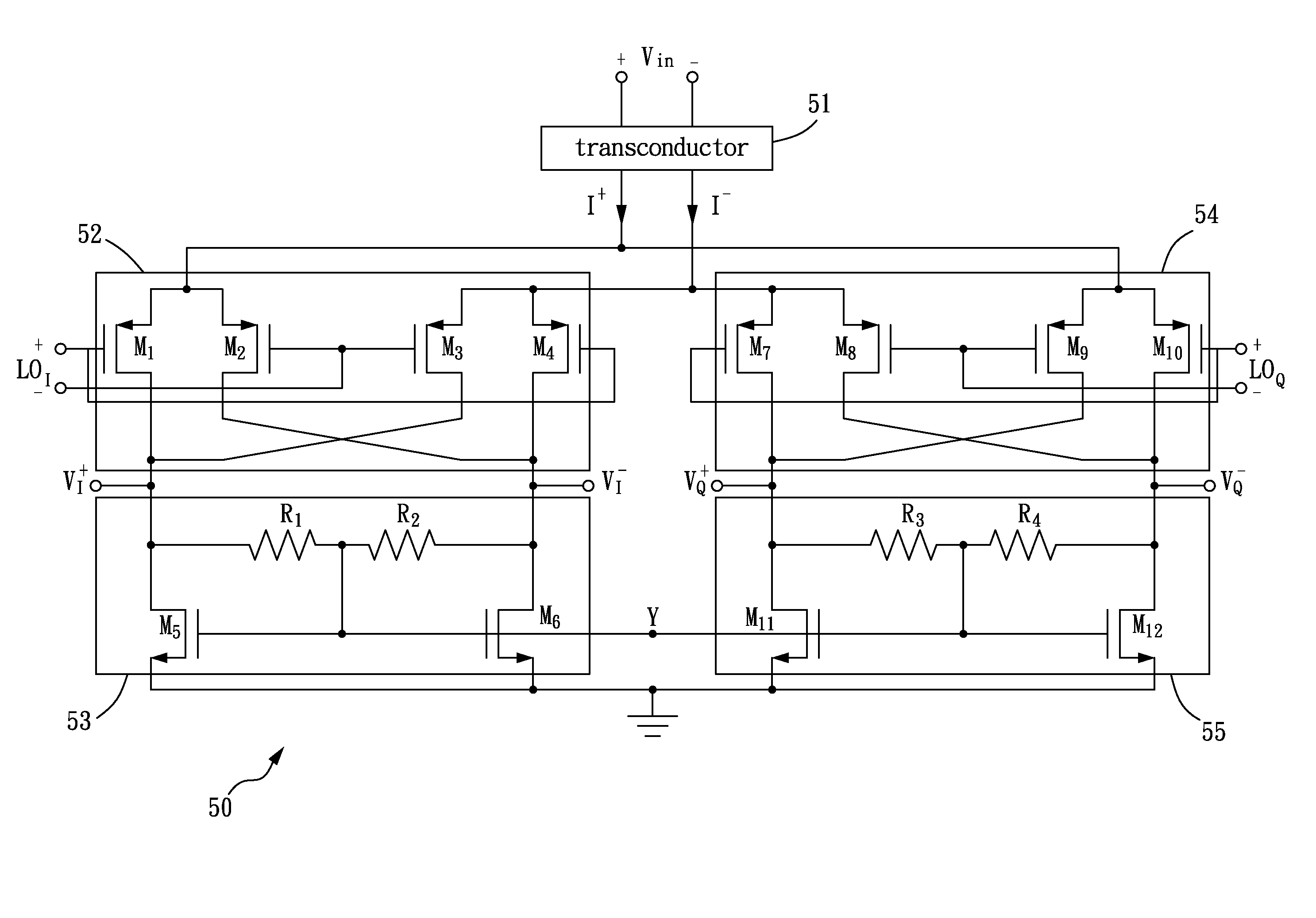
[0022]FIG. 5 is a circuit diagram of a mixer in accordance with the present invention. A mixer 50 comprises a transconductor circuit 51, a first switch circuit 52, a first load circuit 53, a second switch circuit 54, and a second load circuit 55. The transconductor circuit 51 receives differential voltage signals Vin+ and Vin− and correspondingly outputs differential current signals I+ and I−, which are respectively referred to as a first current signal and a second current signal in the following description. The first switch circuit 52 comprises four p-channel transistors M1, M2, M3 and M4. Whether to allow the passing of the first current signal is controlled by the transistors M1 and M2 according to a local oscillator LOI, and whether to allow the passing of the second current signal is controlled by the transistors M3 and M4 according to the local oscillator signal LOI. Accordingly, the first switch circuit 52 converts a frequency of the differential current signal into a summa...

second embodiment

[0029]FIG. 6 is a circuit diagram of a mixer in accordance with the present invention. A mixer 60 comprises a transconductor circuit 61, a switch circuit 62, a load circuit 63, a capacitance unit 64 and a bias circuit 65. The transconductor circuit 61 comprises a bias circuit 611, and the capacitance unit 64 comprises capacitors C1 and C2. The mixer 60 performs a frequency conversion of an input voltage Vin according a local oscillator signal LO to generate an output voltage Vout. The main characteristic of the mixer 60 is that the transconductor circuit 61 and the switch circuit 62 have their own bias circuits to bias independently. That is, the transconductor circuit 61 and the switch circuit 62 respectively decide bias points as needed, so that an issue of swaying the linearity of the transconductor circuit in the prior art, due to the non-independent bias points of the transconductor circuit and the switch circuit, is eliminated. In addition, the capacitors C1 and C2 of the capa...


PUM


Abstract

A mixer includes a transduction circuit, a first and a second switch circuit, and a first and a second load circuit. The transconductor circuit is for generating a differential current signal according to a differential voltage signal. The first switch circuit and the first load circuit are connected in series, and the first switch circuit is used to regulate the differential current signal in response to a first oscillator signal. The second switch circuit and a second load circuit are connected in series, and the second switch circuit is used to regulate the differential current signal in response to a second oscillator signal. The first load circuit and the second load circuit are connected at a common node to reduce harmonic interferences.

Description

CROSS REFERENCE TO RELATED PATENT APPLICATION[0001]This patent application is based on Taiwan, R.O.C. patent application No. 98106350 filed on Feb. 27, 2009.FIELD OF THE INVENTION[0002]The present invention relates to a mixer, and more particularly, to a mixer capable of improving signal quality.BACKGROUND OF THE INVENTION[0003]In a wireless transmitter or a wireless receiver, a mixer is widely used as a frequency conversion device. FIG. 1 shows a conventional wireless transmitter 10 capable of converting a base-band transmitting signal to a radio frequency (RF) transmitting signal to be transmitted via an antenna. The wireless transmitter 10 comprises filters 11 and 12, programmable gain amplifiers 13 and 14, mixers 15 and 16, and a power amplifier 17. After removing needless frequency components from a base-band transmitting signal I by the filter 11, the base-band transmitting signal I is amplified by the programmable gain amplifier 13 and then sent to the mixer 15, where the bas...

Claims


Application Information

Patent Timeline
Patent Type & Authority Applications(United States)
IPC IPC(8): G06G7/16
CPCG06G7/16H03D7/1441H03D7/1458H03D2200/0043H03D7/1491H03D7/165H03D7/1483
Inventor CHOU, CHUNG-YUNYANG, CHAO-TUNG
Owner MEDIATEK INC
Why Eureka
Try Eureka