Method for manufacturing hub unit and hub unit

Active Publication Date: 2010-09-02
JTEKT CORP
View PDF20 Cites 5 Cited by
  • Summary
  • Abstract
  • Description
  • Claims
  • Application Information

AI Technical Summary

Benefits of technology

[0045]According to the hub unit and the hub unit manufacturing method of the present invention, the processing sizes of the members need not be highly accurate or it is not necessary to carry out the dimensional measurement of the shaft, the dimensional measurement of the

Problems solved by technology

So, a great deal of time is necessary for the measurements and there is obstructive i

Method used


Image

  • Method for manufacturing hub unit and hub unit
  • Method for manufacturing hub unit and hub unit
  • Method for manufacturing hub unit and hub unit

Examples


Embodiment Construction

[0057]The present invention will be described in detail below by the embodiments shown in the drawings.

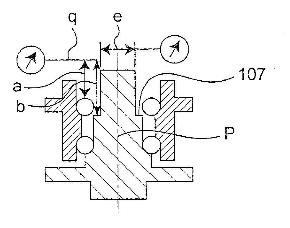
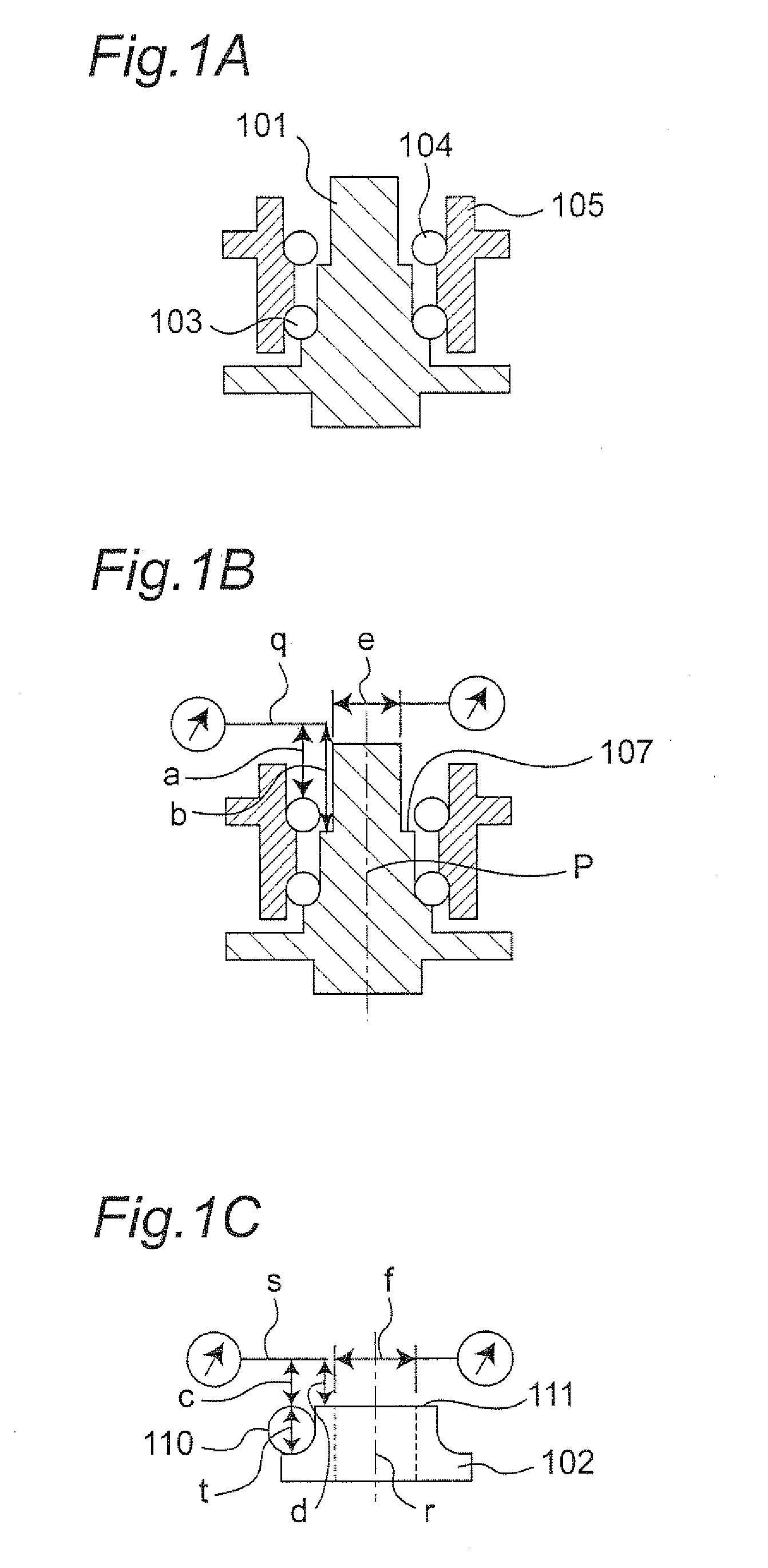
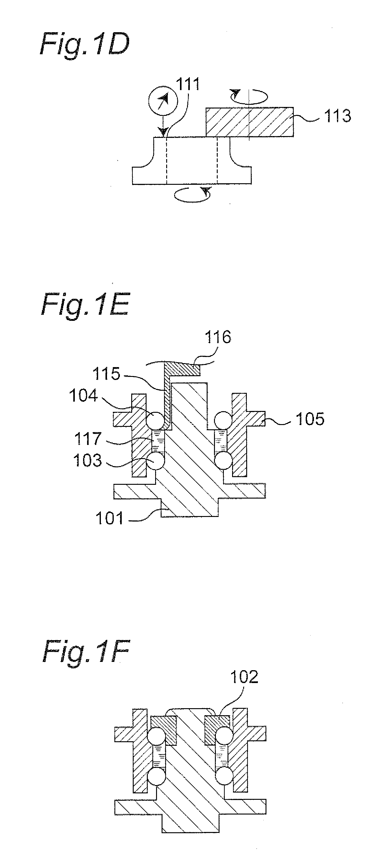
[0058]FIGS. 1A through 1F are views for explaining the hub unit manufacturing method of one embodiment of the present invention.

[0059]The hub unit manufacturing method of the one embodiment of the present invention is described below with reference to FIGS. 1A through 1F. In FIGS. 1A through 1F, 101 indicates a shaft, 102 indicates an inner ring, 103 indicates a first ball as one example of the first rolling element, 104 indicates a second ball as one example of the second rolling element and 105 indicates an outer ring.

[0060]First of all, a subassembly step is carried out. In the subassembly step, the shaft 101, the outer ring 105, the first ball 103 and the second ball 104 are assembled so that the first ball 103 is assembled in between the outer peripheral raceway surface of the shaft 101 and a first inner peripheral raceway surface of the outer ring 105, and the second ball 104...


PUM

PropertyMeasurementUnit
Temperatureaaaaaaaaaa
Diameteraaaaaaaaaa
Sizeaaaaaaaaaa

Abstract

In a state in which a first ball 103 is assembled in between a first inner peripheral raceway surface of an outer ring 105 and an outer peripheral raceway surface of a shaft 101, and a second ball 104 is placed in between a second inner peripheral raceway surface of the outer ring 105 and an outer peripheral surface of the shaft 101, a first distance “a” from a plane “q” generally perpendicular to a central axis “p” of the shaft 101 to the second ball 104 and a second distance “b” from the plane “q” to a stepped portion 107 of the shaft 101 are measured. Then, the size in the axial direction of the inner ring 102 is adjusted on the basis of a difference between the first distance “a” and the second distance “b”.

Description

TECHNICAL FIELD[0001]The present invention relates to a hub unit manufacturing method and a hub unit and, in particular, to the third-generation hub unit manufacturing method for mounting an inner ring on one end side of a shaft placed inside the inner periphery of an outer ring and the third-generation hub unit.BACKGROUND ART[0002]Conventionally, when a hub unit is manufactured by assembling a shaft, an inner ring, balls and an outer ring, it is necessary to measure the sizes of the each part in order to cope with variations in the measurement accuracy of the shaft, variations in the measurement accuracy of the inner ring, variations in the measurement accuracy of the outer ring, variations in the size of the balls within specifications thereof, changes in the inner ring raceway size due to press fitting of the inner ring to the shaft, dimensional changes depending on the temperature of each of the shaft, inner ring, balls and outer ring and so on. So, a great deal of time is neces...

Claims


Application Information

Patent Timeline
IPC IPC(8): F16C43/04B23P15/00B23P17/00
CPCB60B27/0005B60B27/0094F16C19/186F16C43/04F16C2326/02F16C2226/60Y10T29/49702Y10T29/4968Y10T29/49682Y10T29/49535Y10T29/49684Y10T29/49771Y10T29/49689F16C2226/36F16C2229/00
Inventor MIURA, HIROYUKIYOSHIKAWA, HIROSHIOHTANI, YASUHIROMURATA, EIJITOMITA, DAISAKU
Owner JTEKT CORP
Why Eureka
Try Eureka