Method and apparatus for supplying energy to a medical device

a technology for medical devices and wireless energy, applied in the direction of exchanging data chargers, prostheses, therapy, etc., can solve the problems of disturbing the intended medical effect of the device, affecting the efficiency of energy transfer, and the energy supplied to the medical device may also increase dramatically, so as to achieve faster charging, increase the life of the charge occasion, and increase the energy charging rate

Active Publication Date: 2010-09-02
FORSELL PETER
View PDF24 Cites 103 Cited by
  • Summary
  • Abstract
  • Description
  • Claims
  • Application Information

AI Technical Summary

Benefits of technology

[0056]When using the first and second storage devices in the energy storage device, the first storage device may be adapted to be charged at a relatively higher energy charging rate as compared to the second storage device, thereby enabling a relatively faster charging. The first storage device may also be adapted to be charged at multiple individual charging occasions more frequently as compared to the second storage device, thereby providing relatively greater life-time in terms of charging occasions. The first storage device may comprise at least one capacitor. Normally, only the first storage may be charged and more often than needed for the second storage device.
[0057]When the second storage device needs to be charged, to reduce the time needed for charging, the first storage device is charged at multiple individual charging occasions, thereby leaving time in between the charging occasions for the first storage device to charge the second storage device at a relatively lower energy charging rate. When electrical parameters of the medical device are determined, the charging of the second storage device may be controlled based on the parameters. A constant current or stabilizing voltage circuitry may be used for storing energy in the second storage device.

Problems solved by technology

Furthermore, the position of the external energy source relative to the implanted internal energy receiver is a factor that affects the efficiency of the energy transfer, which highly depends on the distance and relative angle between the source and the receiver.
If the transfer efficiency becomes low, the amount of energy supplied to the medical device may be insufficient for operating the device properly, so that its action must be momentarily stopped, naturally disturbing the intended medical effect of the device.
On the other hand, the energy supplied to the medical device may also increase drastically, if the relative positions of the external source and the internal receiver change in a way that unintentionally increases the transfer efficiency.
This situation can cause severe problems since the implant cannot “consume” the suddenly very high amount of supplied energy.
Unused excessive energy must be absorbed in some way, resulting in the generation of heat, which is highly undesirable.
Hence, if excessive energy is transferred from the external energy source to the internal energy receiver, the temperature of the implant will increase, which may damage the surrounding tissue or otherwise have a negative effect on the body functions.
However, the presently available solutions for controlling the wireless transfer of energy to implanted medical devices are lacking in precision in this respect.
However, it is not likely that this solution will work well in practice, since a saturation point in the human tissue would not occur, given the magnetic field levels that are possible to use.
Moreover, if the energy transmission must be increased considerably, e.g. to compensate for losses due to variations in alignment and / or spacing between the coils, the relatively high radiation generated may be damaging or unhealthy or unpleasant to the patient, as is well known.

Method used


Image

  • Method and apparatus for supplying energy to a medical device
  • Method and apparatus for supplying energy to a medical device
  • Method and apparatus for supplying energy to a medical device

Examples


Embodiment Construction

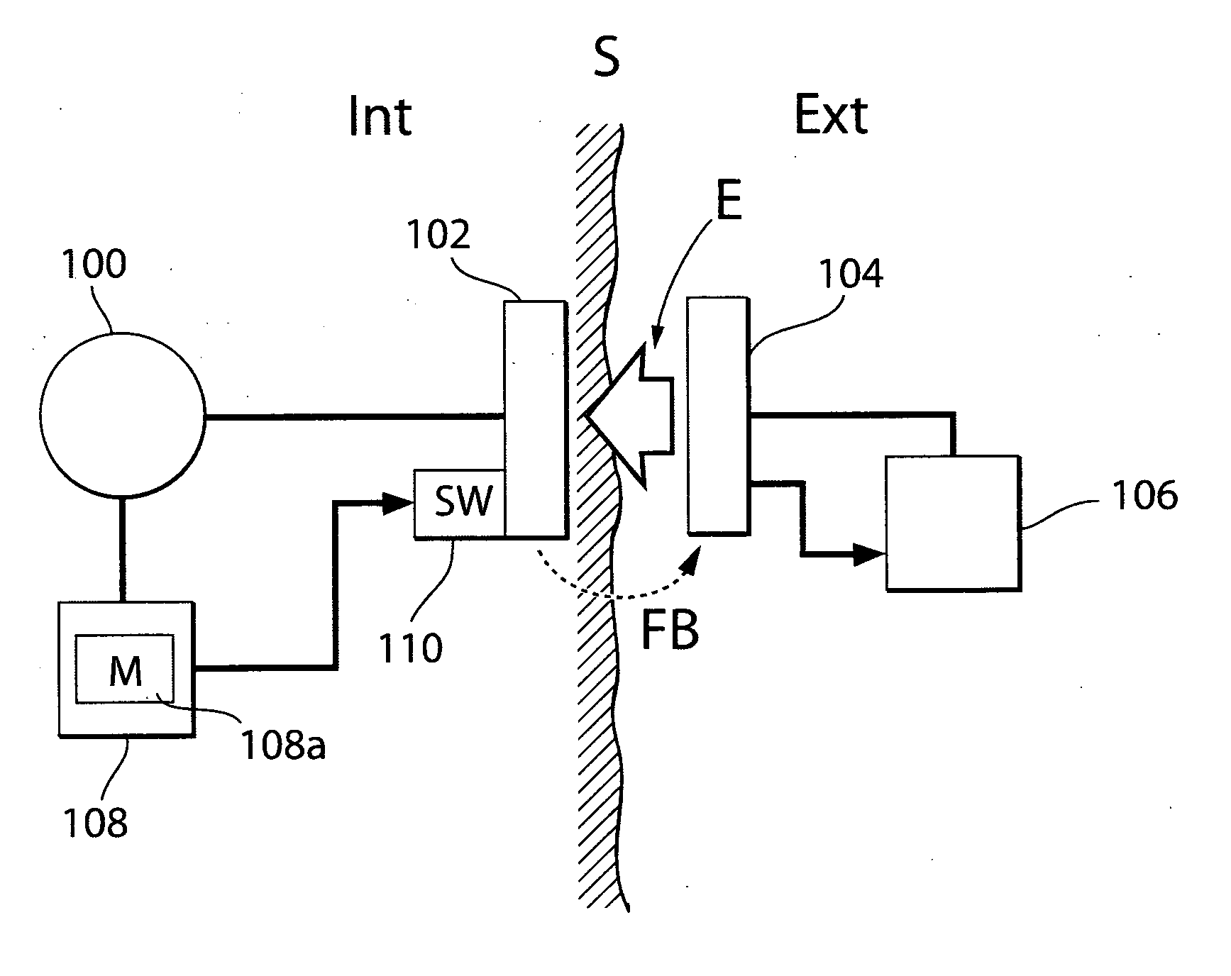
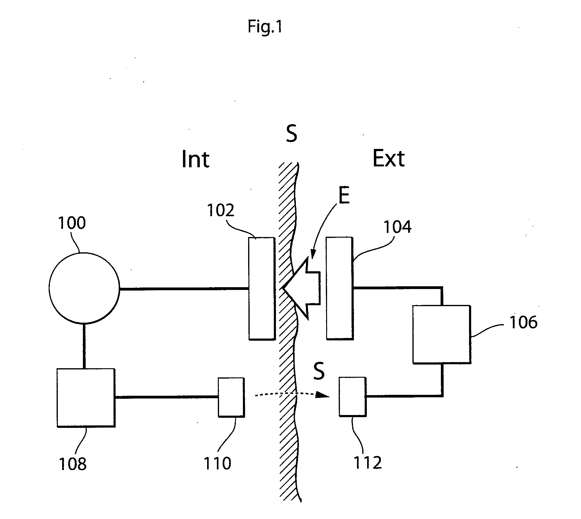
[0090]Briefly described, wireless energy is transmitted from an external energy source located outside a patient and is received by an internal energy receiver located inside the patient. The internal energy receiver is connected to an electrically operable medical device implanted in the patient, for directly or indirectly supplying received energy to the medical device. An energy balance is determined between the energy sent by the external energy source and the energy received by the internal energy receiver, and the transmission of wireless energy is then controlled based on the determined energy balance. The energy balance thus provides an accurate indication of the correct amount of energy needed, which is sufficient to operate the medical device properly, but without causing undue temperature rise.

[0091]In FIG. 1, an arrangement is schematically illustrated for supplying an accurate amount of energy to an electrically operable medical device 100 implanted in a patient, whose ...


PUM


Abstract

In a method and apparatus for supplying wireless energy to a medical device (100) implanted in a patient, wireless energy is transmitted from an external energy source (104) located outside a patient and is received by an internal energy receiver (102) located inside the patient, for directly or indirectly supplying received energy to the medical device. An energy balance is determined between the energy sent by the external energy source and energy received by the internal energy receiver, and the transmission of wireless energy is then controlled based on the determined energy balance. The energy balance thus provides an accurate indication of the correct amount of energy needed, which is sufficient to operate the medical device properly, but without causing undue temperature rise.

Description

TECHNICAL FIELD[0001]The present invention relates generally to a method and apparatus for supplying wireless energy to a medical device implanted in a patient. In particular, the invention is concerned with controlling the amount of energy transferred from an energy source outside the patient to an energy receiver inside the patient.BACKGROUND[0002]Medical devices, designed to be implanted in a patient's body, are typically operated by means of electrical power. Such medical devices include electrical and mechanical stimulators, motors, pumps, etc, which are designed to support or stimulate various body functions. Electrical power can be supplied to such an implanted medical device from a likewise implanted battery or from an external energy source that can supply any needed amount of electrical power intermittently or continuously without requiring repeated surgical operations.[0003]An external energy source can transfer wireless energy to an implanted internal energy receiver loc...

Claims


Application Information

Patent Timeline
Patent Type & Authority Applications(United States)
IPC IPC(8): A61N1/378
CPCA61F2250/0001H02J5/005A61N1/3787H02J7/00034H02J50/80H02J50/10H02J2310/23
Inventor FORSELL, PETER
Owner FORSELL PETER
Why Eureka
Try Eureka