
Method and apparatus for supplying energy to a medical device

a technology for medical devices and wireless energy, applied in the direction of prosthesis, surgery, therapy, etc., can solve the problems of disturbing the intended medical effect of the device, affecting the efficiency of the energy transfer, and affecting the energy supply to the medical devi

Active Publication Date: 2013-06-11
FORSELL PETER
View PDF30 Cites 63 Cited by
  • Summary
  • Abstract
  • Description
  • Claims
  • Application Information

AI Technical Summary

Benefits of technology

[0057]When using the first and second storage devices in the energy storage device, the first storage device may be adapted to be charged at a relatively higher energy charging rate as compared to the second storage device, thereby enabling a relatively faster charging. The first storage device may also be adapted to be charged at multiple individual charging occasions more frequently as compared to the second storage device, thereby providing relatively greater life-time in terms of charging occasions. The first storage device may comprise at least one capacitor. Normally, only the first storage may be charged and more often than needed for the second storage device.
[0076]The object of the present embodiment is to provide an apparatus adapted to control or a method for controlling the flow of fluids and / or other bodily matter in lumens formed by tissue walls of bodily organs, so as to at least substantially or even completely eliminate the injured tissue wall problems that have resulted from implanted prior art devices that constrict such bodily organs.
[0078]The present invention provides an advantageous combination of constriction and stimulation devices, which results in a two-stage influence on the flow of fluids and / or other bodily matter in the lumen of a bodily organ. Thus, the constriction device may gently constrict the tissue wall by applying a relatively weak force against the wall portion, and the stimulation device may stimulate the constricted wall portion to achieve the desired final influence on the flow in the lumen. The phrase “gently constricting a portion of the tissue wall” is to be understood as constricting the wall portion without substantially hampering the blood circulation in the tissue wall.
[0080]Preferably, the stimulation device is adapted to stimulate different areas of the wall portion as the constriction device constricts the wall portion, and the control device controls the stimulation device to intermittently and individually stimulate the areas of the wall portion. This intermittent and individual stimulation of different areas of the wall portion of the organ allows tissue of the wall portion to maintain substantially normal blood circulation during the operation of the apparatus of the invention.

Problems solved by technology

Furthermore, the position of the external energy source relative to the implanted internal energy receiver is a factor that affects the efficiency of the energy transfer, which highly depends on the distance and relative angle between the source and the receiver.
If the transfer efficiency becomes low, the amount of energy supplied to the medical device may be insufficient for operating the device properly, so that its action must be momentarily stopped, naturally disturbing the intended medical effect of the device.
On the other hand, the energy supplied to the medical device may also increase drastically, if the relative positions of the external source and the internal receiver change in a way that unintentionally increases the transfer efficiency.
This situation can cause severe problems since the implant cannot “consume” the suddenly very high amount of supplied energy.
Unused excessive energy must be absorbed in some way, resulting in the generation of heat, which is highly undesirable.
Hence, if excessive energy is transferred from the external energy source to the internal energy receiver, the temperature of the implant will increase, which may damage the surrounding tissue or otherwise have a negative effect on the body functions.
However, the presently available solutions for controlling the wireless transfer of energy to implanted medical devices are lacking in precision in this respect.
However, it is not likely that this solution will work well in practice, since a saturation point in the human tissue would not occur, given the magnetic field levels that are possible to use.
Moreover, if the energy transmission must be increased considerably, e.g. to compensate for losses due to variations in alignment and / or spacing between the coils, the relatively high radiation generated may be damaging or unhealthy or unpleasant to the patient, as is well known.

Method used


Image

  • Method and apparatus for supplying energy to a medical device
  • Method and apparatus for supplying energy to a medical device
  • Method and apparatus for supplying energy to a medical device

Examples


implementation examples

Description of Possible Implementation Examples

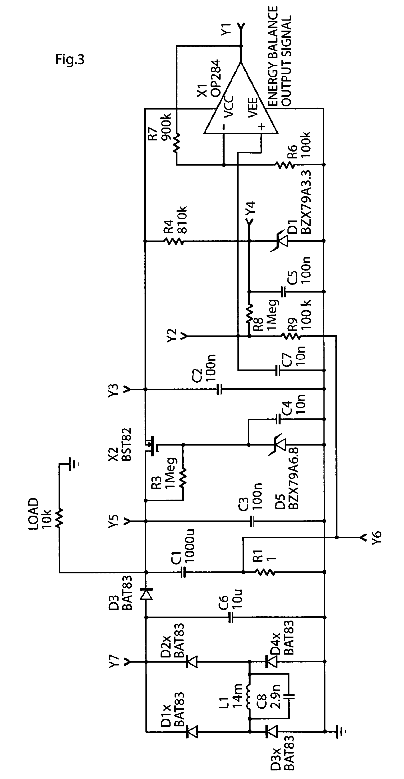
[0200]The schematic FIG. 3 shows a circuit diagram of one of the proposed designs of the invented apparatus for controlling transmission of wireless energy, or energy balance control system. The schematic shows the energy balance measuring circuit that has an output signal centered on 2.5V and that is proportional to the energy imbalance. A signal level at 2.5V means that energy balance exists, if the level drops below 2.5V energy is drawn from the power source in the implant and if the level rises above 2.5V energy is charged into the power source. The output signal from the circuit is typically feed to an ND converter and converted into a digital format. The digital information can then be sent to the external transmitter allowing it to adjust the level of the transmitted power. Another possibility is to have a completely analog system that uses comparators comparing the energy balance level with certain maximum and minimum thresholds...


PUM


Abstract

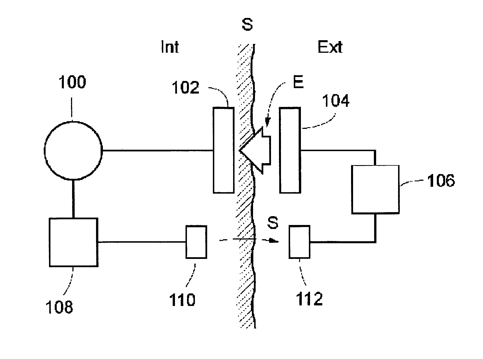
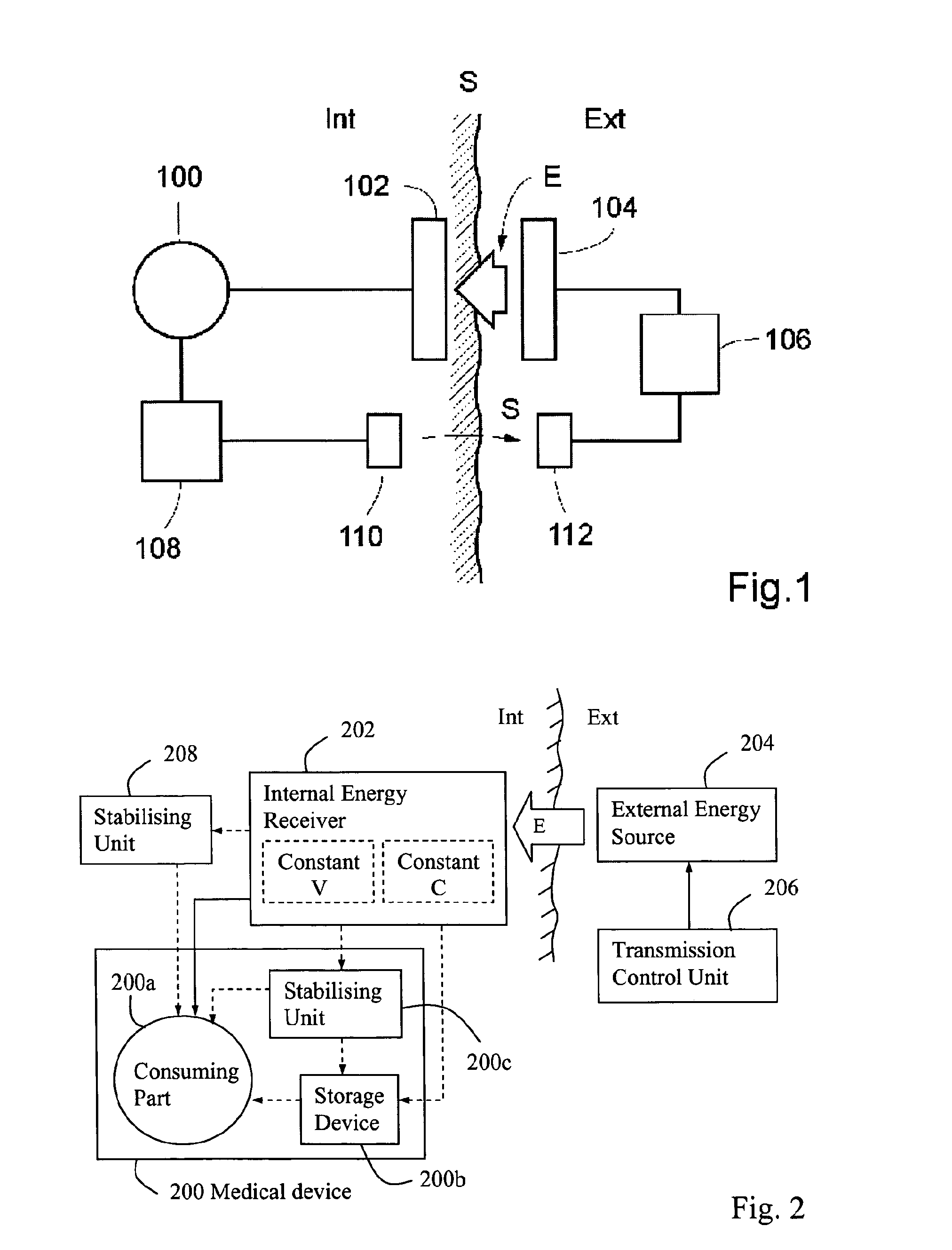
In a method and apparatus for supplying wireless energy to a medical device (100) implanted in a patient, wireless energy is transmitted from an external energy source (104) located outside a patient and is received by an internal energy receiver (102) located inside the patient, for directly or indirectly supplying received energy to the medical device. An energy balance is determined between the energy received by the internal energy receiver and the energy used for the medical device, and the transmission of wireless energy is then controlled based on the determined energy balance. The energy balance thus provides an accurate indication of the correct amount of energy needed, which is sufficient to operate the medical device properly, but without causing undue temperature rise.

Description

[0001]This application is the U.S. national phase of International Application No. PCT / SE2008 / 000561 filed 10 Oct. 2008, which designated the U.S. and claims the benefit of U.S. Provisional Appln. No. 60 / 960,832 filed 16 Oct. 2007, and U.S. Provisional Appln. No. 60 / 960,861 filed 17 Oct. 2007, the entire contents of each of which are hereby incorporated by reference.TECHNICAL FIELD[0002]The present invention relates generally to a method and apparatus for supplying wireless energy to a medical device implanted in a patient. In particular, the invention is concerned with controlling the amount of energy transferred from an energy source outside the patient to an energy receiver inside the patient.BACKGROUND[0003]Medical devices, designed to be implanted in a patient's body, are typically operated by means of electrical power. Such medical devices include electrical and mechanical stimulators, motors, pumps, etc, which are designed to support or stimulate various body functions. Elect...

Claims


Application Information

Patent Timeline
Patent Type & Authority Patents(United States)
IPC IPC(8): A61N1/00
CPCA61N1/08A61N1/3787H02J7/025A61B17/12H02J7/12H02J5/005A61B2560/0214A61F2250/0001H02J2007/0059H02J7/345H04B5/0037H02J7/00034H02J50/10H02J50/80H02J2310/23H02J50/70
Inventor FORSELL, PETER
Owner FORSELL PETER
Learn More