Pneumatic tire
a pneumatic tire and inner block technology, applied in the field of pneumatic tires, can solve the problems of insufficient edge effect, inability to ensure stiffness of outside blocks etc., and achieve the effect of handling performance, inability to ensure stiffness of inside blocks, and inability to ensure outside blocks
- Summary
- Abstract
- Description
- Claims
- Application Information
AI Technical Summary
Benefits of technology
Problems solved by technology
Method used
Image

Examples
modified example 1
[0035]The circumferential sipes 9 (the inside circumferential sipes 9A and the outside circumferential sipes 9B) in the above-described embodiment extend along the tire circumferential direction in zigzag patterns. However, the circumferential sipes can be modified as described below. Note that different points from the pneumatic tire 1 in the above-described embodiment will be mainly explained hereinafter.
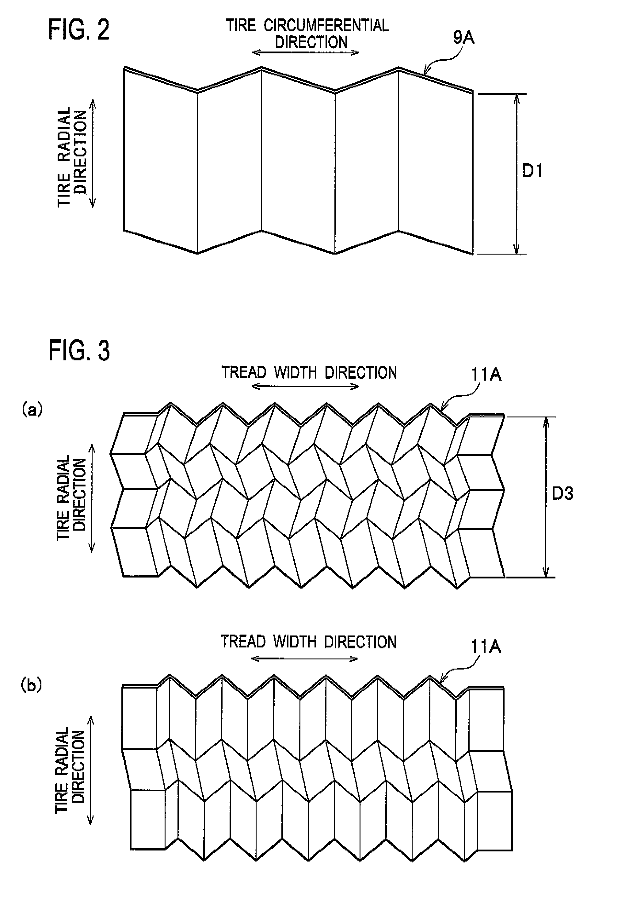
[0036]As shown in FIG. 6(a), the inside circumferential sipes 9A extend straight along the tire circumferential direction. Also in this case, the inside circumferential sipes 9A extend straight along the tire radial direction.
[0037]In addition, as shown in FIG. 6(b), the outside circumferential sipes 98 extend straight along the tire circumferential direction. Also in this case, the outside circumferential sipes 9B extend along the tire radial direction in zigzag patterns.
modified example 2
[0038]In addition, the present invention goes beyond the above modified embodiment. The lateral sipes 11 (the inside lateral sipes 11A and the outside lateral sipes 11B) in the above-described embodiment extend along the tire width direction in zigzag patterns. However, the lateral sipes can be modified as described below.
[0039]As shown in FIG. 7(a), the inside lateral sipes 11A extend straight along the tread width direction. Also in this case, the inside lateral sipes 11A extend along the tire radial direction in zigzag patterns.
[0040]In addition, as shown in FIG. 7(b), the outside lateral sipes 11B extend straight along the tread width direction. Also in this case, the outside lateral sipes 11B extend straight along the tire radial direction.
modified example 3
[0041]In addition, the present invention goes beyond the above modified embodiments and can be modified as described below.
[0042]In the above-described embodiment, all the inside lateral sipes 11A extend along the tire radial direction in zigzag patterns. However, the inside lateral sipes are not limited to this configuration. At least some of the inside lateral sipes 11A may extend along the tire radial direction in zigzag patterns.
[0043]For example, as shown in FIG. 1, only the inside lateral sipes 11A in the blocks 7 located in tread shoulder areas S may extend along the tire radial direction in zigzag patterns. In addition, only the inside lateral sipes 11A in the blocks 7 located in tread middle areas M between a tread center area C and the tread shoulder areas S may extend along the tire radial direction in zigzag patterns.
[0044]In addition, in the above-described embodiment, all the outside circumferential sipes 9B extend along the tire radial direction in zigzag patterns. Ho...
PUM
 Abstract
Description
Claims
Application Information
 - R&D
- Intellectual Property
- Life Sciences
- Materials
- Tech Scout
- Unparalleled Data Quality
- Higher Quality Content
- 60% Fewer Hallucinations
Browse by: Latest US Patents, China's latest patents, Technical Efficacy Thesaurus, Application Domain, Technology Topic, Popular Technical Reports.
© 2025 PatSnap. All rights reserved.Legal|Privacy policy|Modern Slavery Act Transparency Statement|Sitemap|About US| Contact US: help@patsnap.com