Brake system and method for controlling a brake system

a brake system and brake technology, applied in the field of brake systems, can solve the problems of requiring a greater effort on the part of the driver, the recuperative braking system is often not able to exert a braking torque on the wheels of the vehicle, and the operation of the electric motor in generator mode typically requires a certain minimum speed of the vehicle, so as to achieve stable braking performance, improve the distribution of brake force, and improve the effect of handling performan

Active Publication Date: 2017-04-25
ROBERT BOSCH GMBH
View PDF27 Cites 1 Cited by
  • Summary
  • Abstract
  • Description
  • Claims
  • Application Information

AI Technical Summary

Benefits of technology

[0013]Thus, by using a sensor or by applying an estimation, it is possible to ascertain which total braking torque is desired by the driver, which actual recuperative braking torque is exerted by the recuperative brake, which hydraulic braking torque is applied by the conventional braking system, and what difference still exists between the desired total braking torque and the active recuperative braking torque. The braking torque corresponding to the ascertained difference may subsequently be exerted by the control valve on the first wheel. This renders possible a blending, without the driver having to expend additional work for that purpose. Thus, a sufficient recuperation efficiency is ensured at reasonable cost.
[0015]In addition, a use of the exemplary embodiments and / or exemplary methods of the present invention is practical for a dynamic braking in a curve. In the case of dynamic curve braking, the braking force at a wheel on the inside of the curve is increased relative to the braking force at a wheel on the outside of the curve. This achieves a more dynamic handling performance.
[0016]In addition, the exemplary embodiments and / or exemplary methods of the present invention may also be used for a more advantageous braking when driving in reverse. In particular, by increasing the braking force at the rear axle, a better brake-force distribution is adjusted for a driving in reverse. In this context, one also speaks of a reverse brake-force distribution. Most notably, this permits a substantially more stable braking performance in the case of a slow reverse travel on a downgrade.
[0018]In addition, the exemplary embodiments and / or exemplary methods of the present invention at least better ensures that an option is provided for improving the pedal feel by decoupling the first brake circuit, so that the driver no longer needs to control the first brake circuit directly via a force that is exerted on the brake pedal. The pedal travel is also able to be shortened in this manner. The exemplary embodiments and / or exemplary methods of the present invention offers a simple-to-implement and inexpensive alternative to a conventional brake-by-wire brake system that, in particular, is very advantageous for rear-wheel-drive or all-wheel-drive vehicles. However, the exemplary embodiments and / or exemplary methods of the present invention may also be used for the front-wheel drive featuring a by-wire front-wheel axle.
[0021]In another specific embodiment, an output of the control valve and an output of the separator valve are coupled to a second branch point, a first wheel-inlet valve being configured between the second branch point and the first wheel-brake cylinder that is designed to direct the inflow of the brake medium from the second branch point to the first wheel-brake cylinder. In this manner, it is possible to reliably control the build-up of a brake pressure at the first wheel-brake cylinder.
[0025]In another exemplary embodiment, the second brake circuit is switchable into a first state and a second state, which are designed in such a way that a driving of the second pump of the second brake circuit that is switched into the first state effects a change in pressure at the second wheel-brake cylinder, and a driving of the second pump of the second brake circuit that is switched into the first state effects a circulating flow of the brake medium in the second brake circuit. This is able to be implemented, for example, in that the second brake circuit has a nonreturn valve configured between the switchover valve and the second pump, and a valve configured in parallel to the second pump, the second brake circuit being switchable by a closing of the valve into the first state and by an opening of the valve into the second state. This ensures that there is another option for preventing an undesired joint operation of the second pump in the case of a driving of the first pump by the motor.

Problems solved by technology

Moreover, operating the electric motor in generator mode typically requires a certain minimum speed of the vehicle.
Therefore, a recuperative braking system is frequently not able to exert a braking torque on the wheels of a vehicle until the vehicle traveling ahead is at a standstill.
However, this process requires a greater expenditure of effort on the part of the driver.
However, conventional brake-by-wire brake systems are expensive due to the complex electronics and mechanics / hydraulics that they require.

Method used


Image

  • Brake system and method for controlling a brake system
  • Brake system and method for controlling a brake system
  • Brake system and method for controlling a brake system

Examples


Embodiment Construction

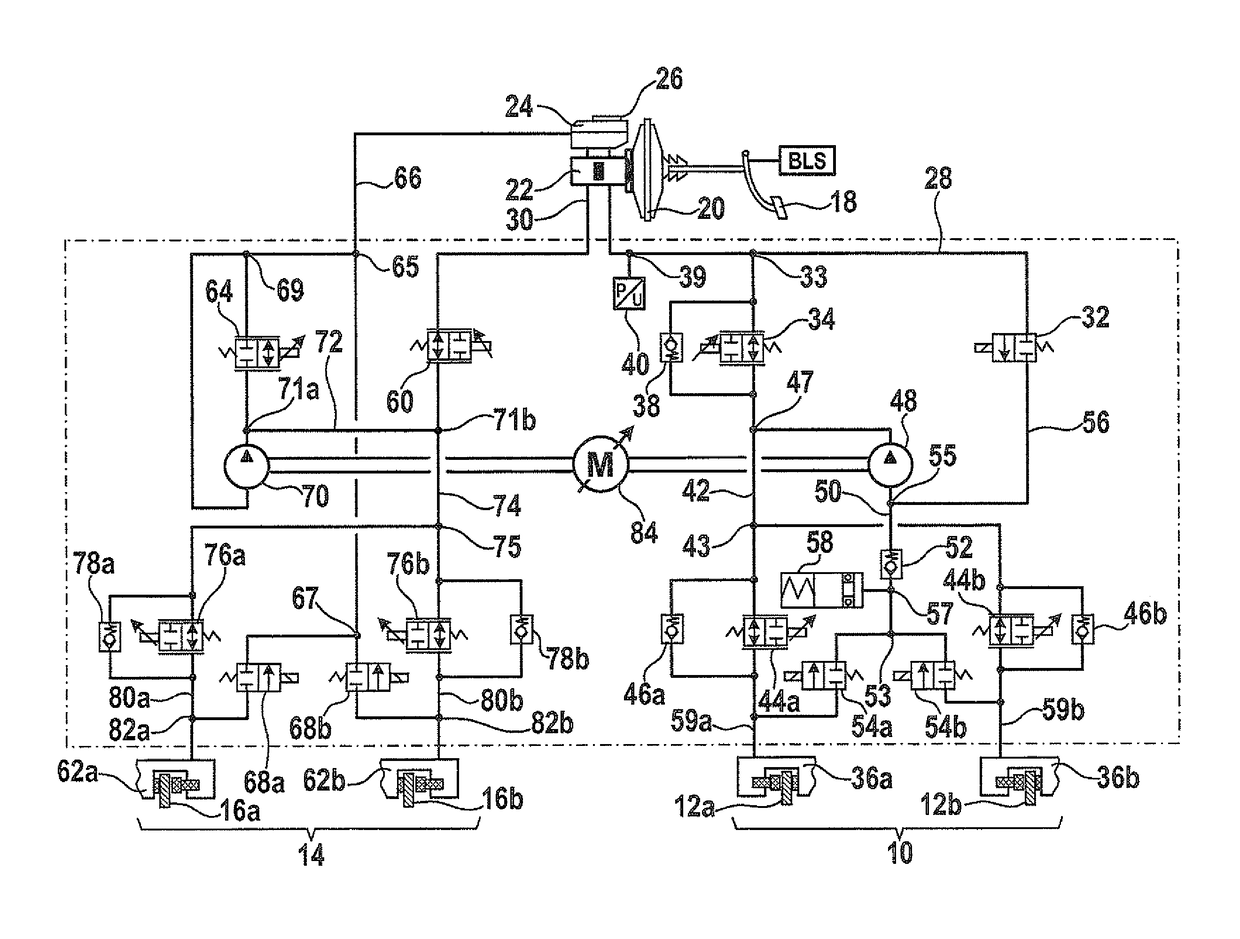
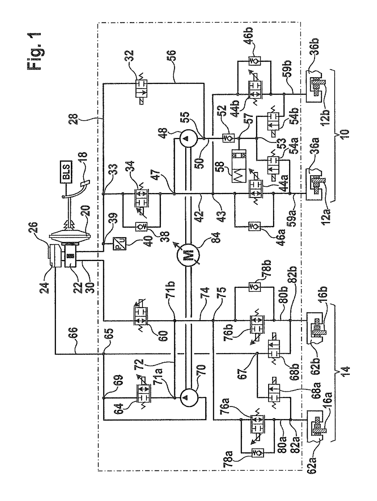
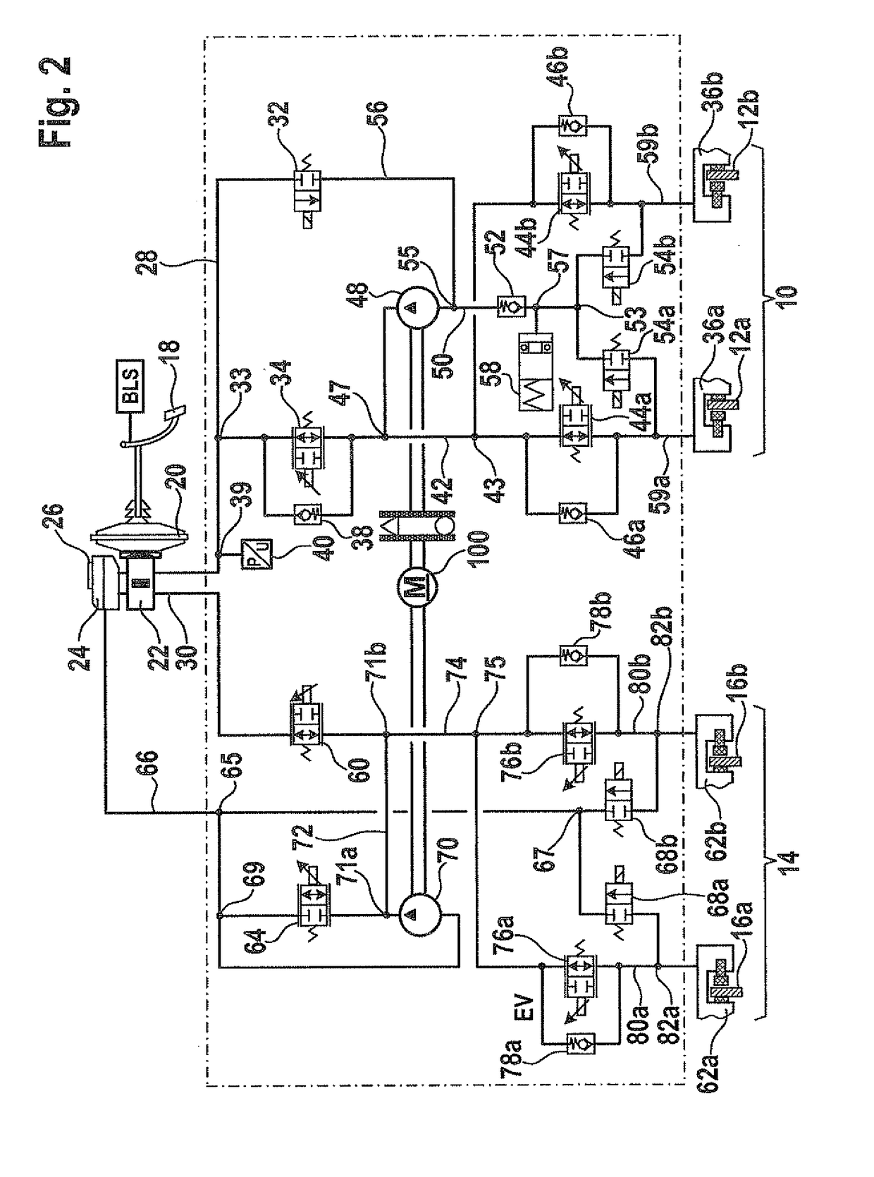
[0031]The brake system described in the following paragraphs is not only suited for use in a hybrid vehicle. Instead, the brake system may also be used in conventional vehicles, for example, to ensure a brake-force distribution at the wheels of the vehicle in the case of a braking during cornering and / or a travel in reverse.

[0032]FIG. 1 shows a circuit diagram of a first specific embodiment of the brake system.

[0033]The brake system illustrated in FIG. 1 encompasses a front brake circuit 10 for braking front wheels 12a and 12b and a rear brake circuit 14 for braking rear wheels 16a and 16b. However, the illustrated example is not limited to this distribution of wheels 12a, 12b, 16a and 16b. It is self-evident that the example is also applicable to a specific embodiment where wheels 12a and 12b are the rear wheels and wheels 16a and 16b are the front wheels of a vehicle. Wheels 12a and 12b and wheels 16a and 16b may also be two pairs of wheels that are configured on two different sid...


PUM


Abstract

A brake system for a vehicle having a master brake cylinder, which provides a pressure signal, having a brake-medium reservoir connected to the master brake cylinder, and a first brake circuit, which is coupled by a first input to the master brake cylinder and by a second input to the brake-medium reservoir, and having at least one first wheel brake cylinder, which is mounted at a first wheel, in order to exert a force corresponding to the pressure signal onto the first wheel, and having a separator valve, which is configured between the first input and the first wheel-brake cylinder, to prevent further transmission of the pressure signal upon receipt of a supplied closing signal; and having a control valve, which is configured between the first input and the first wheel-brake cylinder; in order to control an inflow of a brake medium from brake-medium reservoir to the first wheel-brake cylinder. In addition, a method for controlling a corresponding brake system is also described.

Description

FIELD OF THE INVENTION[0001]The present invention relates to a brake system for a motor vehicle. In addition, the present invention relates to a method for controlling a brake system for a motor vehicle.BACKGROUND INFORMATION[0002]Hybrid vehicles have a brake system that is designed for recuperative braking. In recuperative braking, an electric motor of the hybrid vehicle, typically, the electric drive motor, is operated in generator mode. Following an intermediate storage, the electrical energy recovered during recuperative braking may be used for an acceleration of the vehicle. This reduces any power loss experienced by a conventional vehicle due to frequent braking during a drive. As a result, the energy consumption and the pollutant emissions of the hybrid vehicle are reduced in comparison to the conventional vehicle.[0003]To ensure that the recuperative braking have as little effect as possible on the braking distance of the vehicle, it is necessary that the braking system of t...

Claims


Application Information

Patent Timeline
Patent Type & Authority Patents(United States)
IPC IPC(8): B60T13/74B60T8/48B60L7/00B60T8/36B60T8/40
CPCB60T8/4872B60L7/003B60T8/3655B60T8/4054B60T8/4072B60T8/1755B60T8/176B60T8/1766B60T2270/60B60L7/18B60T8/267B60T11/22B60T13/145B60T13/686B60T13/745B60T2270/604B60T2270/82
Inventor WUERTH, GEBHARDMEHL, VOLKERKUNZ, MICHAELLEIBLEIN, MATTHIASQUIRANT, WERNER
Owner ROBERT BOSCH GMBH
Why Eureka
Try Eureka