
Brake system and method for controlling a brake system

a brake system and brake technology, applied in the direction of brake systems, brake components, transportation and packaging, etc., can solve the problems of requiring a greater effort on the part of the driver, the recuperative braking system is often not able to exert a braking torque on the wheels of the vehicle, and the electric motor operating in generator mode typically requires a certain minimum speed, so as to improve the brake performance and improve the brake performance. the effect of distributing the for

Active Publication Date: 2017-07-06
ROBERT BOSCH GMBH
View PDF8 Cites 0 Cited by
  • Summary
  • Abstract
  • Description
  • Claims
  • Application Information

AI Technical Summary

Benefits of technology

The invention provides a brake system that uses sensors and estimates to determine the driver's desired braking torque, the actual braking torque achieved by the system, and the difference between the two. This difference is then exerted by the control valve on the first wheel, allowing for a seamless blending without the driver having to expend additional effort. The system also improves dynamic braking in curves and ensures a stable braking performance when driving in reverse. Additionally, the invention provides an improved pedal feel and a simple and affordable alternative for rear-wheel-drive or all-wheel-drive vehicles. The invention also includes a brake system that can switch between two states to control brake pressure at the first wheel-brake cylinder.

Problems solved by technology

Moreover, operating the electric motor in generator mode typically requires a certain minimum speed of the vehicle.
Therefore, a recuperative braking system is frequently not able to exert a braking torque on the wheels of a vehicle until the vehicle traveling ahead is at a standstill.
However, this process requires a greater expenditure of effort on the part of the driver.
However, conventional brake-by-wire brake systems are expensive due to the complex electronics and mechanics / hydraulics that they require.

Method used


Image

  • Brake system and method for controlling a brake system
  • Brake system and method for controlling a brake system
  • Brake system and method for controlling a brake system

Examples


Embodiment Construction

[0030]The brake system described in the following paragraphs is not only suited for use in a hybrid vehicle. Instead, the brake system may also be used in conventional vehicles, for example, to ensure a brake-force distribution at the wheels of the vehicle in the case of a braking during cornering and / or a travel in reverse.

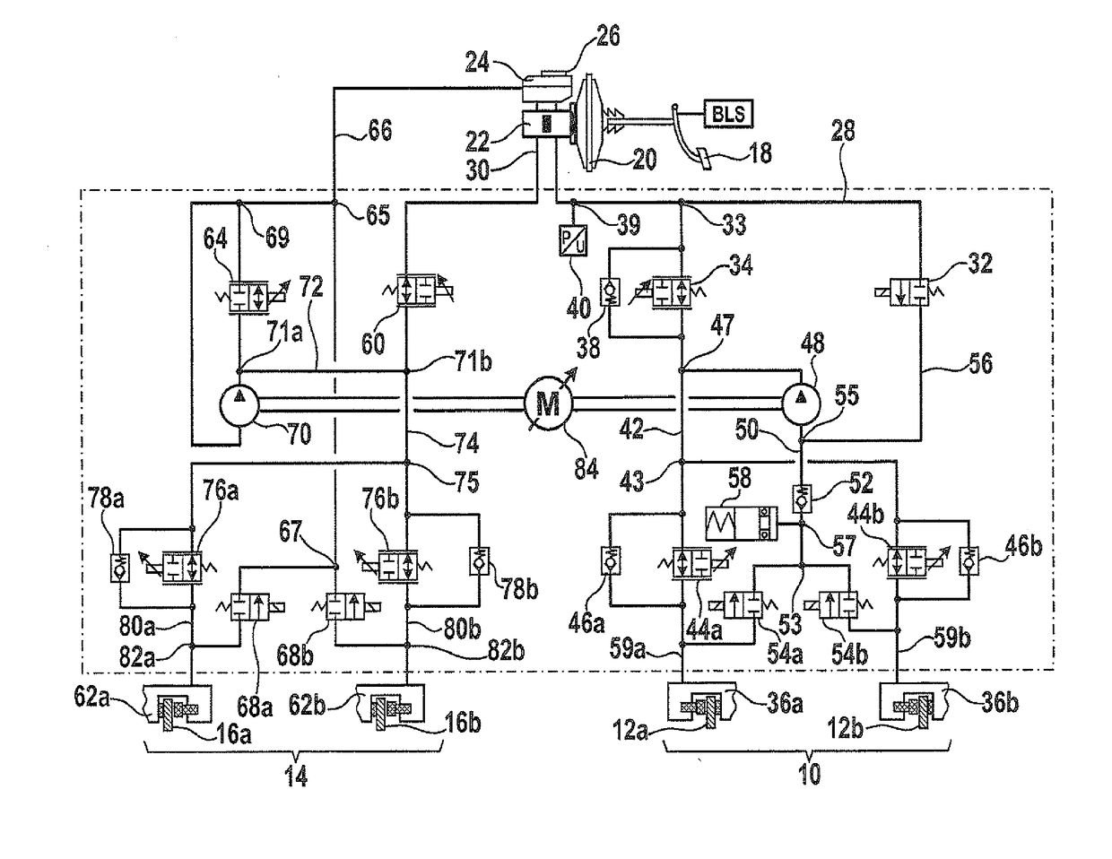
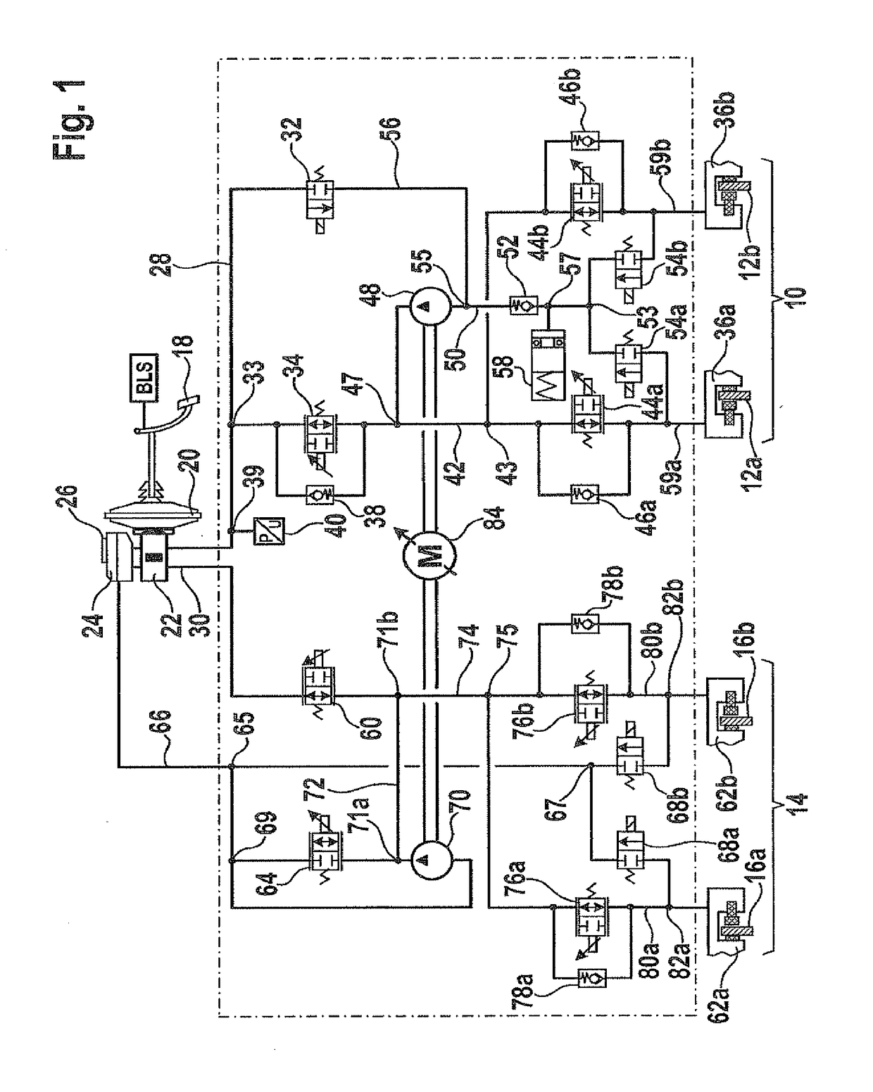
[0031]FIG. 1 shows a circuit diagram of a first specific embodiment of the brake system.

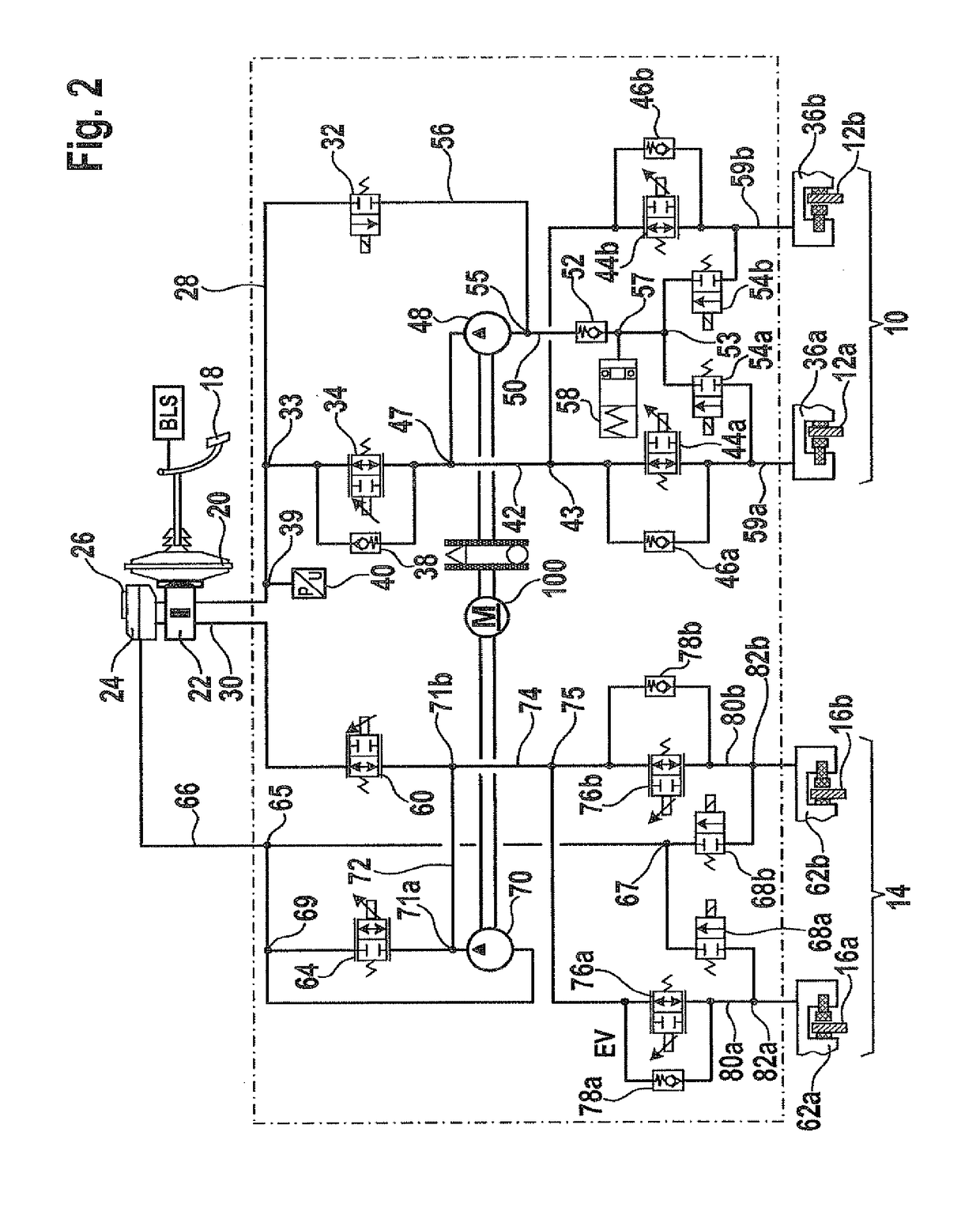
[0032]The brake system illustrated in FIG. 1 encompasses a front brake circuit 10 for braking front wheels 12a and 12b and a rear brake circuit 14 for braking rear wheels 16a and 16b. However, the illustrated example is not limited to this distribution of wheels 12a, 12b, 16a and 16b. It is self-evident that the example is also applicable to a specific embodiment where wheels 12a and 12b are the rear wheels and wheels 16a and 16b are the front wheels of a vehicle. Wheels 12a and 12b and wheels 16a and 16b may also be two pairs of wheels that are configured on two different sid...


PUM


Abstract

A brake system for a vehicle having a master brake cylinder, which provides a pressure signal, having a brake-medium reservoir connected to the master brake cylinder, and a first brake circuit, which is coupled by a first input to the master brake cylinder and by a second input to the brake-medium reservoir, and having at least one first wheel-brake cylinder, which is mounted at a first wheel, in order to exert a force corresponding to the pressure signal onto the first wheel, and having a separator valve, which is configured between the first input and the first wheel-brake cylinder, to prevent further transmission of the pressure signal upon receipt of a supplied closing signal; and having a control valve, which is configured between the first input and the first wheel-brake cylinder; in order to control an inflow of a brake medium from brake-medium reservoir to the first wheel-brake cylinder. In addition, a method for controlling a corresponding brake system is also described.

Description

CROSS REFERENCE TO RELATED APPLICATIONS[0001]The present application is a continuation application of U.S. patent application Ser. No. 12 / 811,745, filed Jul. 6, 2010, which is a national phase to International Application No. PCT / EP2008 / 065519, filed Nov. 14, 2008, and claims priority to German Patent Application No. 10 2008 004 201.3, filed Jan. 14, 2008, all of which are hereby incorporated by reference in their entireties.FIELD OF THE INVENTION[0002]The present invention relates to a brake system for a motor vehicle. In addition, the present invention relates to a method for controlling a brake system for a motor vehicle.BACKGROUND INFORMATION[0003]Hybrid vehicles have a brake system that is designed for recuperative braking. In recuperative braking, an electric motor of the hybrid vehicle, typically, the electric drive motor, is operated in generator mode. Following an intermediate storage, the electrical energy recovered during recuperative braking may be used for an accelerati...

Claims


Application Information

Patent Timeline
Patent Type & Authority Applications(United States)
IPC IPC(8): B60T8/26B60L7/18B60T13/14B60T13/74B60T11/22B60T13/68
CPCB60T8/267B60T11/22B60T13/686B60T2270/604B60T13/745B60L7/18B60T2270/82B60T13/145B60T8/1755B60T8/176B60T8/1766B60T2270/60B60L7/003B60T8/3655B60T8/4054B60T8/4072B60T8/4872
Inventor WUERTH, GEBHARDMEHL, VOLKERKUNZ, MICHAELLEIBLEIN, MATTHIASQUIRANT, WERNER
Owner ROBERT BOSCH GMBH
Learn More