Multi-channel radio frequency front end circuit with full transmit and receive diversity for multi-path mitigation

a multi-path mitigation and multi-channel technology, applied in the field of radio frequency signal circuitry, can solve problems such as increased risk of bodily harm by accidents, wear and tear of transportation infrastructure, and productivity decline, and achieve the effects of reducing the risk of injury, increasing the risk of physical harm by accidents, and increasing the fuel consumption

Inactive Publication Date: 2010-09-09
SKYWORKS SOLUTIONS INC
View PDF56 Cites 66 Cited by
  • Summary
  • Abstract
  • Description
  • Claims
  • Application Information

AI Technical Summary

Problems solved by technology

Due to population growth and increased mobilization, modern metropolitan areas suffer from substantial congestion that result in decreased productivity, wear to transportation infrastructure, increased fuel consumption, increased risk of bodily harm by accidents, and so forth.
Errors may be caused in part by increased noise from the surrounding environment, obstacles, and so forth.
Even minor transmission delays that result from the above-mentioned retry attempts may have dire consequences for the lives of vehicle occupants due to the spe...

Method used


Image

  • Multi-channel radio frequency front end circuit with full transmit and receive diversity for multi-path mitigation
  • Multi-channel radio frequency front end circuit with full transmit and receive diversity for multi-path mitigation
  • Multi-channel radio frequency front end circuit with full transmit and receive diversity for multi-path mitigation

Examples


first embodiment

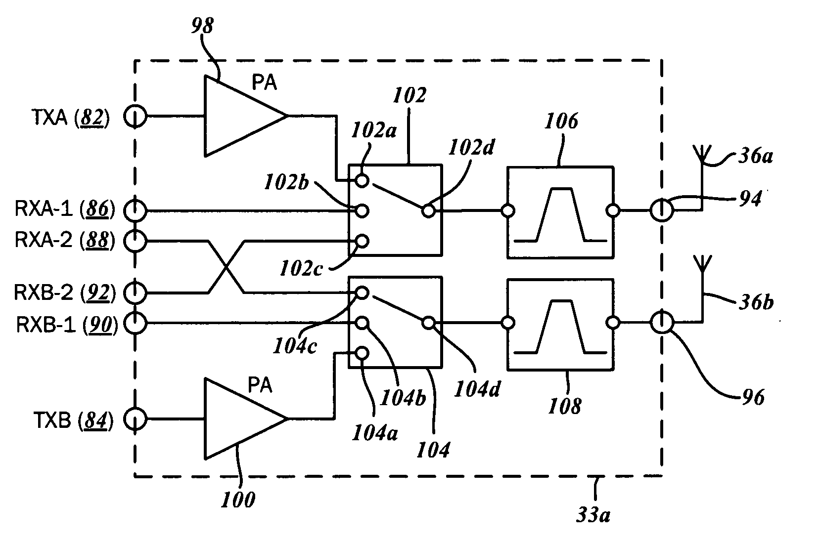
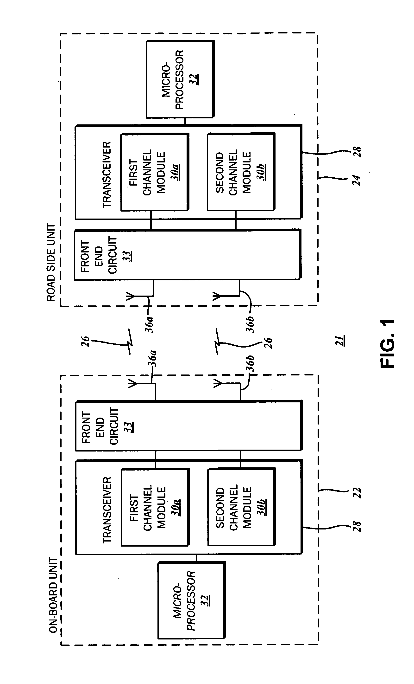
[0045]Having considered the various operational parameters of simultaneous operation, dual-channel time-domain duplex communications systems such as WAVE, further details regarding the various embodiments of the front end module 33 will be described. The schematic diagram of FIG. 7 illustrates the front end module 33a. As discussed above, the front end module 33 is connectable to the transceiver 28 that includes the first channel module 30a for one operational frequency or channel, and the second channel module 30b for the other operational frequency or channel. According to various embodiments, each of the first and second channel modules 30a, 30b includes a transmit line, a primary receive line, and a secondary receive line. The primary receive line and the secondary receive line are understood to be connectable to the two spatially separated antennas 36 for multipath mitigation purposes. This configuration is also referred to as antenna diversity. Along these lines, the front end...

second embodiment

[0073]One variation of the first power divider 124 and the second power divider 126 utilized in the front end module 33b is disclosed in Applicant's co-pending patent application U.S. patent application Ser. No. 12 / 467,049 filed May 15, 2009 entitled RADIO FREQUENCY POWER DIVIDER AND COMBINER CIRCUIT, which is expressly incorporated by reference in its entirety herein. Generally, the power dividers 124, 126 are configured to have a minimal power loss from the common port 124c, 126c to the first split ports 124a, 126a, and to the second split ports 124b, 126b, respectively. One embodiment contemplates a loss of less than 0.5 dB. Additionally, isolation between the first split ports 124a, 126a, and the second split ports 124b, 126b, respectively, is maximized when the common ports 124c, 126c is matched in the operating frequency range. As mentioned above, the power split between the first split port 124a and the second split port 124b, as well as the first split port 126a and the seco...

third embodiment

[0121]FIG. 16 shows an operational sequence of the front end module 33c. It is contemplated that the activation of the first primary receive port 86 is exclusive of the activation of the first transmit port 82 during time period t1. However, since the activation of the first secondary receive port 88 is independent of the first transmit port 82, the two can be activated simultaneously. The activation of the second primary receive port 90 is exclusive of the activation of the second transmit port 84 during the time period t2. The activation of the second secondary receive port 92 is also independent of the second transmit port 84, and the two can likewise be activated simultaneously.

[0122]During a time period 252 in which the first transmit port 82 is activated and the second transmit port 84 is not activated, the first secondary receive port 88 and the second primary receive port 90 have a period of reduced sensitivity 254, as there is no antenna diversity. Additionally, the period ...


PUM


Abstract

A front end circuit for coupling a plurality of antennas to a multi-channel time domain duplex RF transceiver is disclosed. The front end circuit has a first transmit port, a first receive chain primary port, a first receive chain secondary ports, and a first antenna port connectable to a first one of the plurality of antennas. The front end circuit also has a second transmit port, a second receive chain primary port, and a second receive chain secondary port connectable to a second one of the plurality of antennas. A first switch has terminals connected to the first transmit port, the first receive chain primary port, and the second receive chain secondary port, as well as a common terminal that is connected to the first antenna port. Additionally, the front end circuit has a second switch that has terminals connected to the second transmit port, the second receive chain primary port and the first receive chain secondary port, and a common terminal connected to the second antenna port.

Description

CROSS-REFERENCE TO RELATED APPLICATIONS[0001]This application is a continuation of U.S. application Ser. No. 12 / 470,960 filed May 22, 2009, entitled MULTI-CHANNEL RADIO FREQUENCY FRONT END CIRCUIT which relates to and claims the benefit of U.S. Provisional Application No. 61 / 156,954, filed Mar. 3, 2009 and entitled DUAL-CHANNEL (DUAL FREQUENCY) HIGH-SENSITIVITY RF FRONT-END ARCHITECTURES FOR WAVE AND OTHER TDD APPLICATIONS, each of which are wholly incorporated by reference herein.STATEMENT RE: FEDERALLY SPONSORED RESEARCH / DEVELOPMENT[0002]Not ApplicableBACKGROUND[0003]1. Technical Field[0004]The present invention relates generally to radio frequency (RF) signal circuitry, and more particularly, to multi-channel / frequency front-end integrated circuits for time domain duplex communications.[0005]2. Related Art[0006]Due to population growth and increased mobilization, modern metropolitan areas suffer from substantial congestion that result in decreased productivity, wear to transporta...

Claims


Application Information

Patent Timeline
IPC IPC(8): H01P1/10
CPCH04B1/48H04B7/0817H04B7/0602
Inventor GORBACHOV, OLEKSANDR
Owner SKYWORKS SOLUTIONS INC
Why Eureka
Try Eureka