
Navigation apparatus and navigation method

Active Publication Date: 2010-09-09
SONY CORP
View PDF10 Cites 54 Cited by
  • Summary
  • Abstract
  • Description
  • Claims
  • Application Information

AI Technical Summary

Benefits of technology

[0007]The present invention has been made in consideration of the above points. It is desirable to propose a navigation apparatus and navigation method which allows a user to easily recognize where a characteristic point is actually located from a user's view.
[0009]By this means, it is possible for a user to recognize the distance and the direction of a characteristic point on a captured image that the user is viewing and checking in accordance with a distance line indicating a distance from the current position. It is therefore possible for the user to recognize where the characteristic point is actually located from a user's view without being forced to do a difficult task which relates a scene that the user is actually viewing to a map on a plane.
[0010]By the present invention, it is possible for a user to recognize the distance and the direction of a characteristic point on a captured image that the user is viewing and checking in accordance with a distance line indicating a distance from the current position. Accordingly, it is possible to achieve a navigation apparatus and navigation method allowing the user to easily recognize where the characteristic point is actually located from a user's view without being forced to do a difficult task which relates a scene that the user is actually viewing to a map on a plane.

Problems solved by technology

Incidentally, in a related-art PND described above, it is difficult for a user to understand a relationship between a scene that the user is actually seeing and a map on a plane.
Also, even if the user can check a characteristic point on a map, there has been a problem in that it is difficult for the user to recognize where the characteristic point is actually located from a user's view.

Method used


Image

  • Navigation apparatus and navigation method
  • Navigation apparatus and navigation method
  • Navigation apparatus and navigation method

Examples


embodiment

1. Embodiment

1.1 Outer Configuration of PND

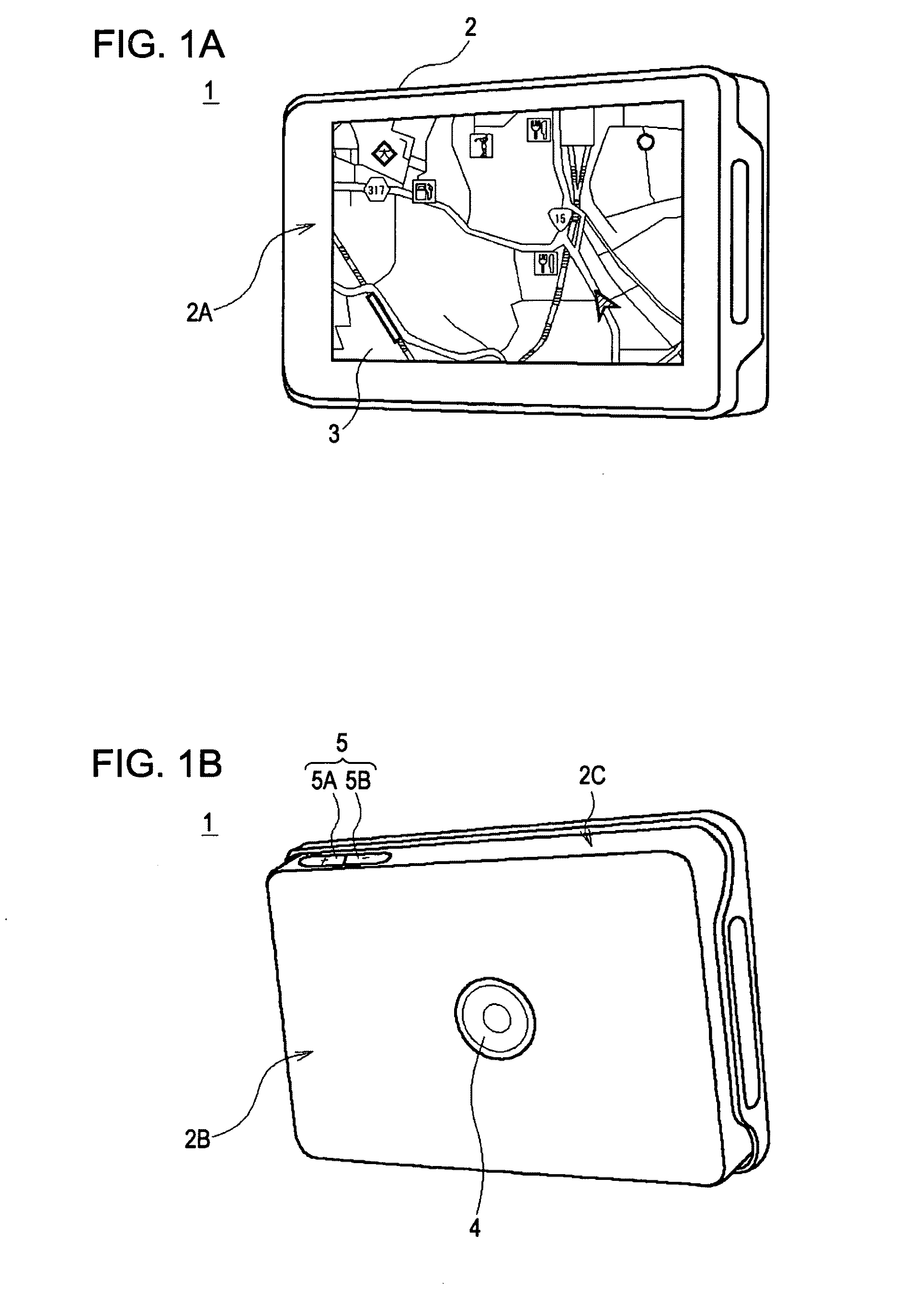
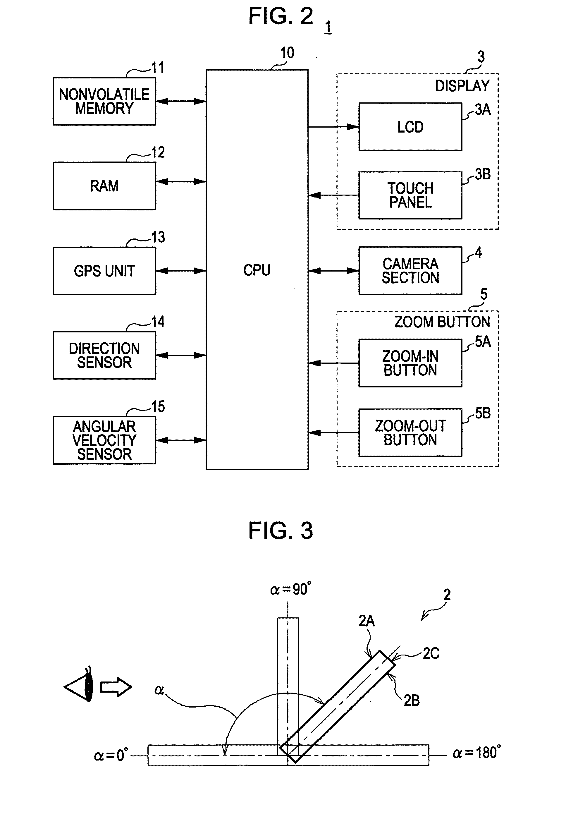
[0030]In FIGS. 1A and 1B, reference numeral 1 denotes an overall portable navigation device (hereinafter referred to as a PND) according to the present invention. The PND 1 (FIG. 1A) includes a substantially cuboid-shaped case 2. A display 3 is disposed on a front face 2A of the case 2.

[0031]The case 2 has about a size that a user can carry about in his / her single hand and check the display 3 while walking.

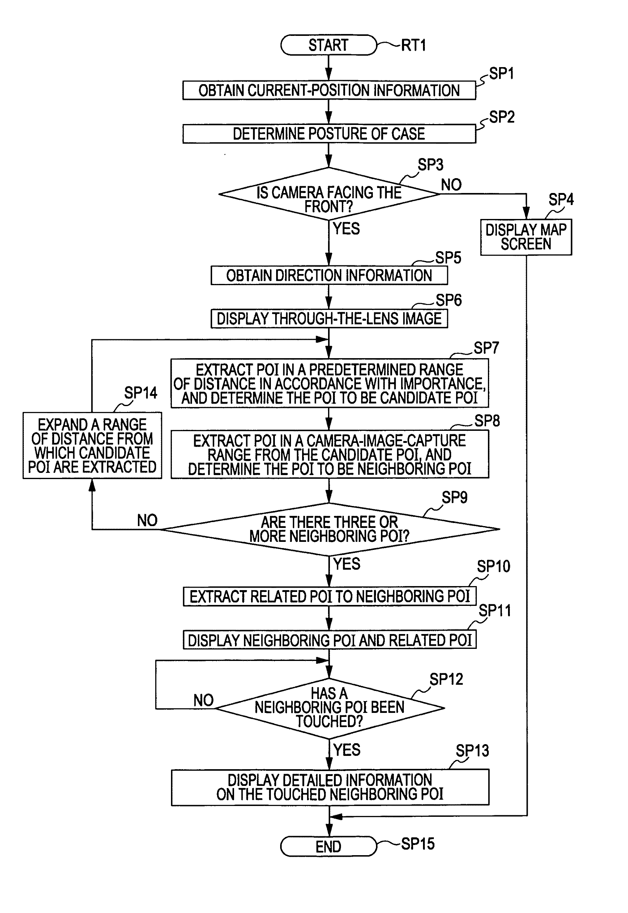
[0032]A camera section 4 is disposed on a back face 2B (FIG. 1B) of the case 2. The PND 1 displays, in real time, a captured image (also referred to as a through-the-lens image) of a subject (neighboring scene) taken by the camera section 4 on the display 3.

[0033]Also, zoom buttons 5 (a zoom-in button 5A and a zoom-out button 5B) are disposed on a top face 2C of the case 2. The PND 1 expands and contracts the through-the-lens image displayed on the display 3 in accordance with a user's pressing operation on the zoom buttons 5.

1.2 Circuit ...


PUM


Abstract

A navigation apparatus includes: a current-position information acquisition section obtaining measured current-position information; a camera section obtaining a captured image of a subject; a direction detection section detecting a direction when obtaining the captured image by the camera section; from characteristic-point information related to multiple predetermined characteristic points stored in a storage section, a characteristic-point information extraction section extracting the characteristic-point information related to the characteristic points located in the vicinity of the current position and in a range shown in the direction; and a control section displaying the captured image on a display section, wherein the control section displays a predetermined direction line indicating a distance from the current position on the captured image, obtains a distance and a direction from the current position to the characteristic point, and displays the characteristic-point information at a position corresponding to the distance and the direction on the captured image.

Description

BACKGROUND OF THE INVENTION[0001]1. Field of the Invention[0002]The present invention relates to a navigation apparatus and navigation method, and is preferably applied to a portable navigation device which is handy to carry about, for example.[0003]2. Description of the Related Art[0004]To date, a portable navigation device (hereinafter, referred to as a PND) displays predetermined characteristic-points, such as various facilities (public facilities, recreational facilities, various stores, etc.) and mountains, etc., on a map so as to allow a user to check these characteristic points. These characteristic points are generally called POI (Points of Interest). Elements constituting each POI include a name, a latitude and longitude, an address, a genre, a telephone number, a URL (Uniform Resource Locator), etc.[0005]Also, there is a portable guiding apparatus which displays a simulation image of a scene that is assumed to be seen by a user, and displays POI in the vicinity of the user...

Claims


Application Information

Patent Timeline
IPC IPC(8): H04N7/18G06T11/20G09G5/00
CPCG01C21/3602G01C21/3647G01C21/3682
Inventor MIYATA, HIROMASA
Owner SONY CORP
Learn More