
Image-Output Control Device, Method of Controlling Image-Output, Program for Controlling Image-Output, and Printing Device

Inactive Publication Date: 2009-10-01
SEIKO EPSON CORP
View PDF3 Cites 12 Cited by
  • Summary
  • Abstract
  • Description
  • Claims
  • Application Information

AI Technical Summary

Benefits of technology

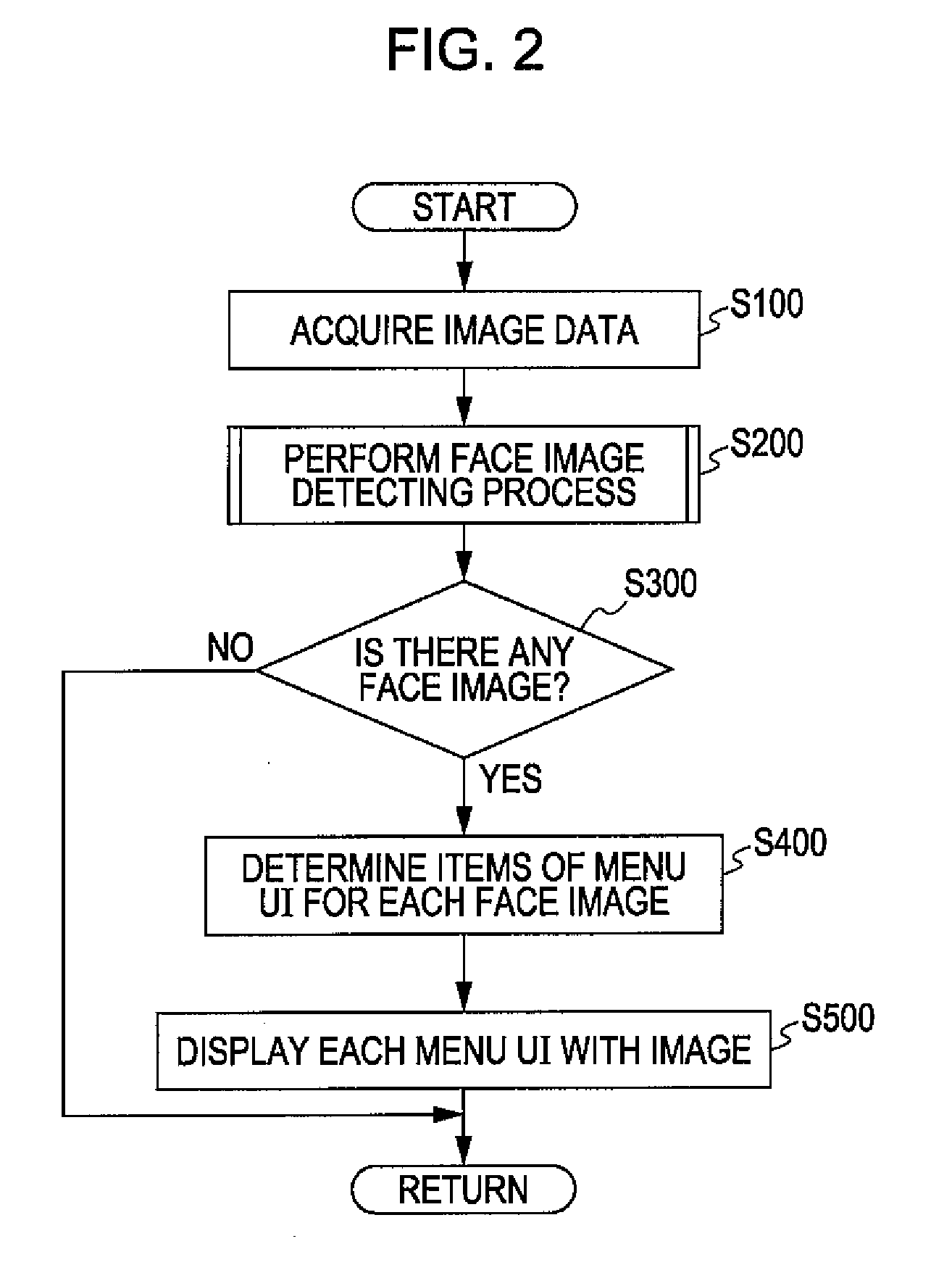
[0007]An advantage of some aspects of the invention is that it provides an image-output control device, a method of controlling image output, an image-output control program, and a printing device capable of allowing a user to easily recognize and perform selection of processes appropriate to each predetermined image such as a face image.
[0008]According to a first aspect of the invention, there is provided an image-output control device including: a detection unit that detects a predetermined image from a target image; and an output control unit that outputs menu display, which is a menu display that can receive selection of a process to be performed for the target image and the predetermined image, for each predetermined image detected from the target image to a predetermined output target. According to the image-output control device, even when a plurality of predetermined images is detected from the target image, menu display for each predetermined image is output to the output target. Accordingly, a user can recognize selection of a process appropriate to each predetermined image in an easy manner by watching the menu display, and thereby appropriate selection can be made.
[0010]As an example, it may be configured that the detection unit detects a face image from the target image as the predetermined image, and the output control unit outputs the menu display corresponding to a face image, which is positioned in an approximately front direction, of the detected face image which includes an item of an identification photograph printing process. In addition, the output control unit may be configured to analyze color information for each detected predetermined image and output the menu display corresponding to a predetermined image, for which the result of analysis of the color information corresponds to a predetermined correction condition, which includes an item of a predetermined color correcting process. In addition, the output control unit may be configured to analyze a shape of each detected predetermined image and output the menu display corresponding to a predetermined image, for which the result of analysis of the shape corresponds to a predetermined correction condition, which includes an item of a predetermined shape correcting process. In such a case, the user does not need to be bothered for checking whether each predetermined image is appropriate as an ID photo, each predetermined image is to be corrected in color, or each predetermined image is to be corrected in shape. In addition, the user can recognize selection of a process that is appropriate to each predetermined image in an easy manner by viewing the items included in each menu display.
[0011]In the above-described image-output control device, the output control unit may be configured to output the target image and the menu display for each predetermined image in a state in which each common reference sign is assigned to the predetermined image and the menu display that are in correspondence with each other. In such a case, the user can visually recognize correspondence relationship between each predetermined image and corresponding menu display in an easy manner.

Problems solved by technology

However, to determine whether an image is appropriate as an ID photo while checking contents of images that is photographed and stored in the memory card one after another is a heavy load for the user.
In particular, when a plurality of images is saved in the memory card, a load needed for the determination is increased further.
In addition, even when a plurality of face images (predetermined images) is included in one image, the user may hesitate to determine a face image that is appropriate as the ID photo.
Furthermore, even when a correction process or the like is performed for an image face, it is too troublesome for the user to determine a correction process that is appropriate to each face image.

Method used


Image

  • Image-Output Control Device, Method of Controlling Image-Output, Program for Controlling Image-Output, and Printing Device
  • Image-Output Control Device, Method of Controlling Image-Output, Program for Controlling Image-Output, and Printing Device
  • Image-Output Control Device, Method of Controlling Image-Output, Program for Controlling Image-Output, and Printing Device

Examples


Embodiment Construction

[0028]An embodiment of the invention will be described in the following order.

[0029]1. Schematic Configuration of Printer

[0030]2. Image Outputting Process[0031]2-1. Detection of Face Image[0032]2-2. Outputting Image to Display Unit[0033]2-3. Process After Image Output

[0034]3. Modified Example

1. Schematic Configuration of Printer

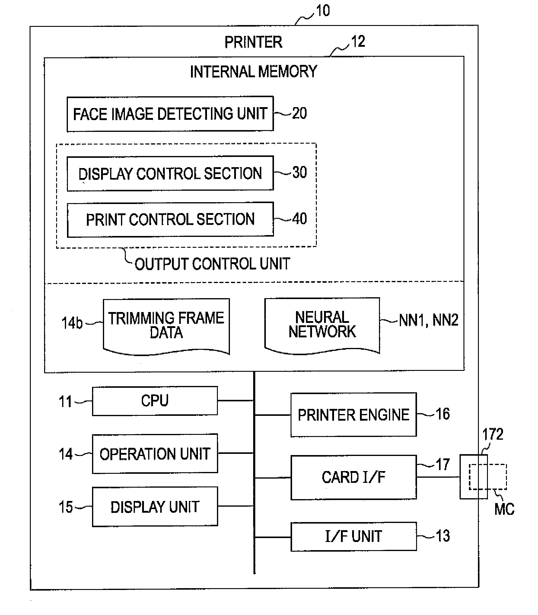
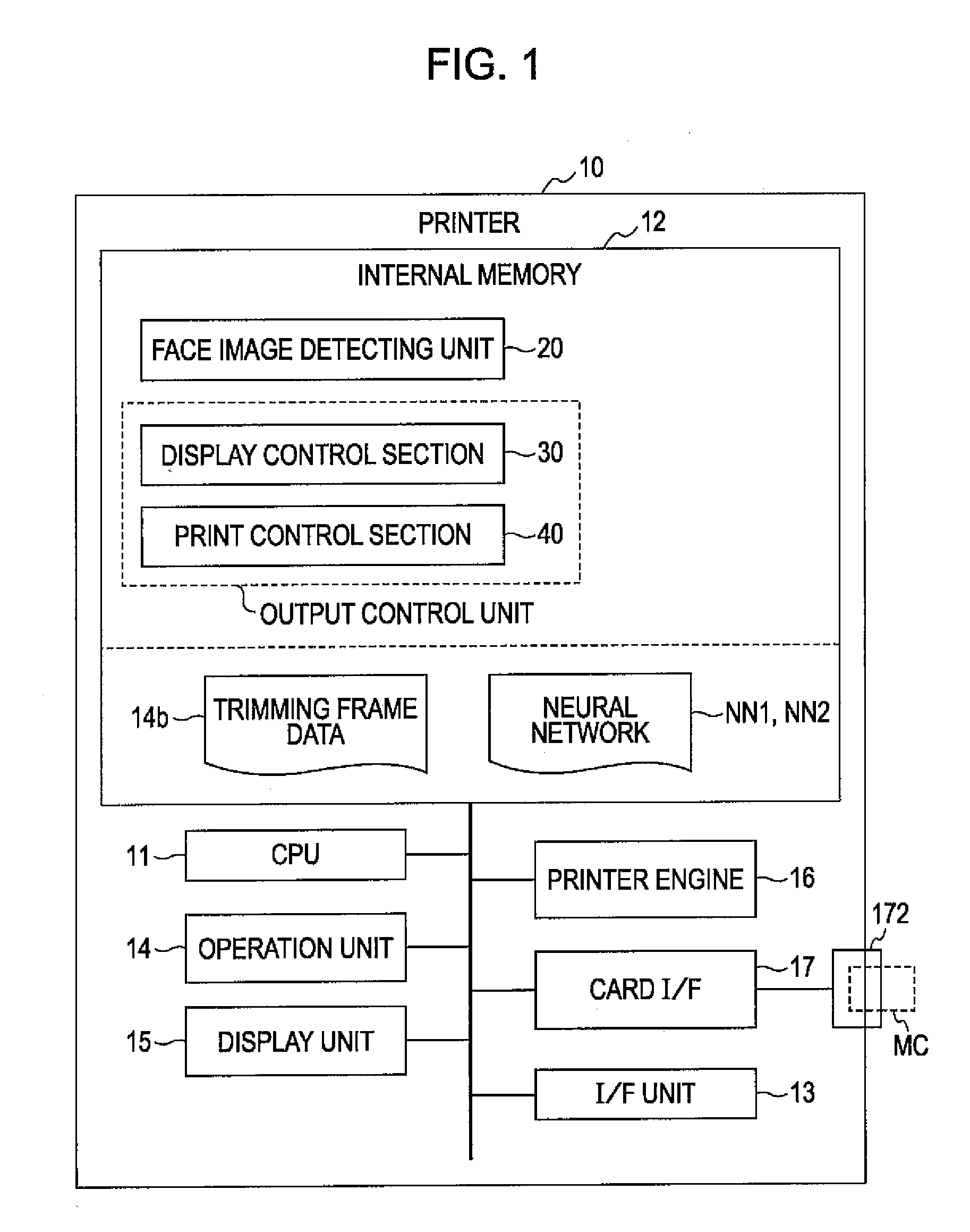
[0035]FIG. 1 schematically shows the configuration of a printer 10 as an example of an image-output control device and a printing device according to an embodiment of the invention. The printer 10 prints an image based on image data that is acquired from a recording medium (for example, a memory card MC or the like) and is a color ink jet printer corresponding to so-called direct printing. The printer 10 includes a CPU 11 that controls other units of the printer 10, an internal memory 12 that is, for example, configured by a ROM and a RAM, and operation unit 14 that is configured by buttons or a touch panel, a display unit 15 that is configured by a liquid cr...


PUM


Abstract

An image-output control device includes a detection unit that detects a predetermined image from a target image and an output control unit that outputs menu display, which is a menu display that can receive selection of a process to be performed for the target image and the predetermined image, for each predetermined image detected from the target image to a predetermined output target.

Description

BACKGROUND[0001]1. Technical Field[0002]The present invention relates to an image-output control device, a method of controlling image output, a program for controlling image output, and a printing device.[0003]2. Related Art[0004]Users print arbitrary photographs (for example, an identification photograph (ID photo) that is used for a resume, a driver's license, a passport, or the like) by using printers. As technology related thereto, a printing device in which a user selects an ID photo mode from a selection screen of a printing mode, then, selection of the type of a printing sheet and the size of an ID photo is received from the user, selection of an image to be printed as the ID photo is received from the user, then, a face area is extracted from the selected image, an area (clip area) including the extracted face area which will be printed as the ID photo is determined, and an image of the clip area is printed on the selected printing sheet has been known (see JP-A-2007-253488...

Claims


Application Information

Patent Timeline
IPC IPC(8): G06F3/12
CPCG06K9/00228H04N1/00265H04N1/00275H04N1/00413H04N1/0044H04N1/00474H04N2201/3277H04N1/00506H04N1/2125H04N2201/3271H04N2201/3273H04N2201/3276H04N1/00482G06V40/161
Inventor TSUJI, HIROYUKI
Owner SEIKO EPSON CORP
Learn More