Apparatus for supporting body part of worker

Inactive Publication Date: 2014-01-16
DENSO CORP +2
View PDF5 Cites 14 Cited by
  • Summary
  • Abstract
  • Description
  • Claims
  • Application Information

AI Technical Summary

Benefits of technology

[0018]Further, in this case, after determining that the body part is in the third condition, the determining means may determine whether or not the condition of the body part has changed to the first condition. Further, after determining that the body part is in the first condition, the determining means may determine whether or not the condition of the body part has changed to the second condition. Also, after determining that the body part is in the second condition, the determining means may det

Problems solved by technology

However, in the apparatus disclosed in JP-A-H10-272163, the surgeon has to unfasten the belt member every time the surgeon is required to remove his/her arm from the support to temporarily place a surgical tool, such as

Method used


Image

  • Apparatus for supporting body part of worker
  • Apparatus for supporting body part of worker
  • Apparatus for supporting body part of worker

Examples


Example

First Embodiment

[0032]With reference to FIGS. 1 to 4, a first embodiment of the body support apparatus will now be described.

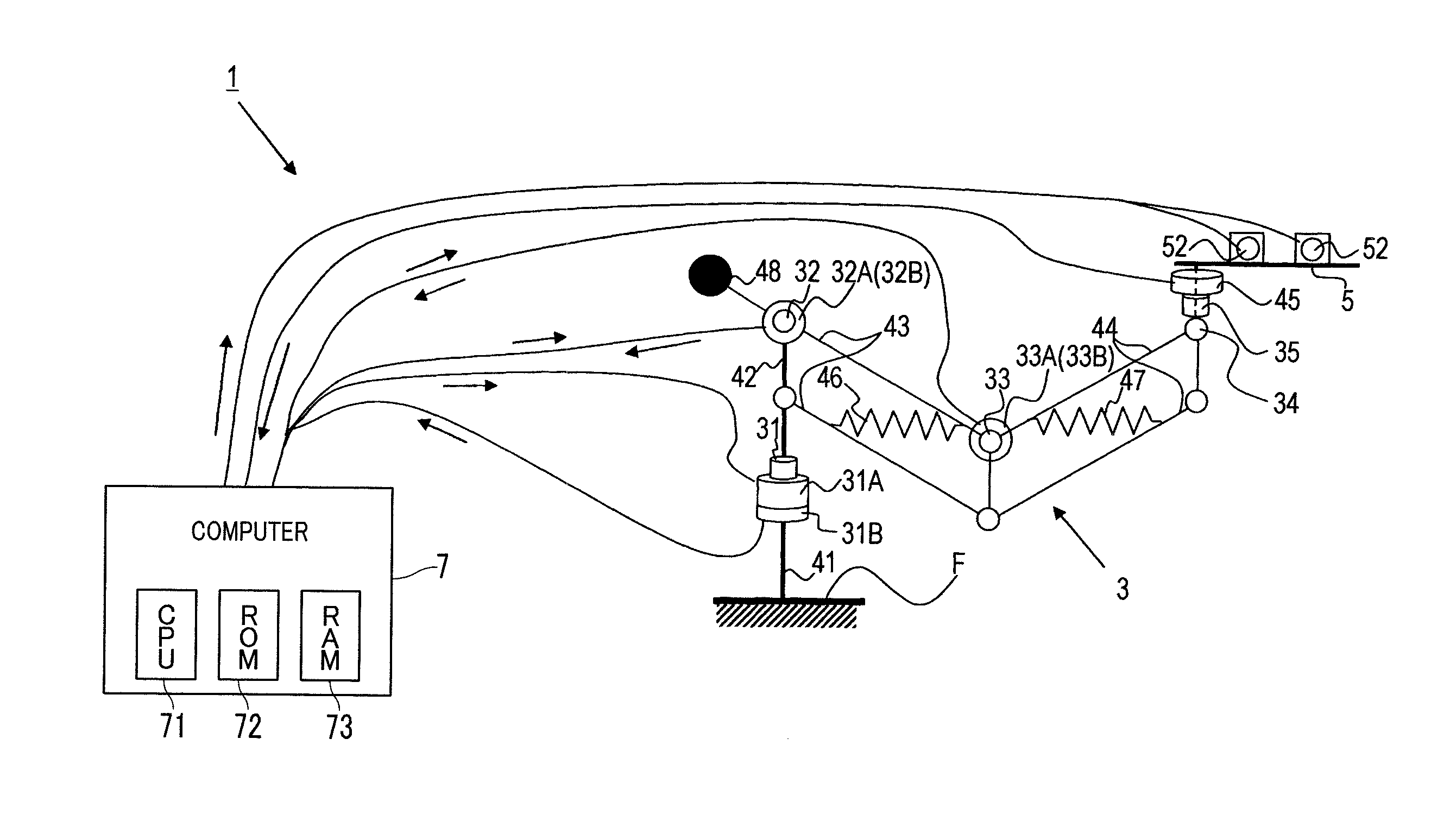
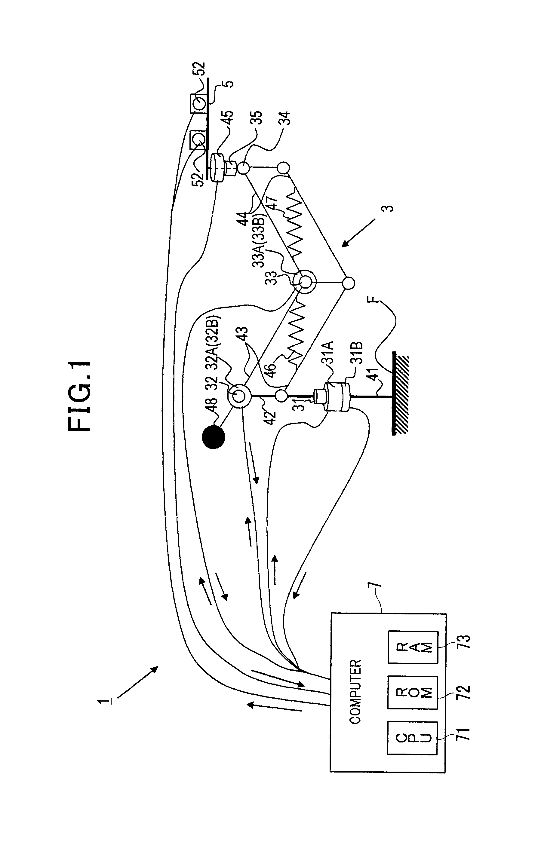
[0033]FIG. 1 is a schematic diagram illustrating a body support apparatus 1 according to a first embodiment. As shown in FIG. 1, the body support apparatus 1 includes a multijoint arm 3 (acting as a support), an end arm 5 mounted to an end of the multijoint arm 3, and a computer 7 that determines a mode for controlling the multijoint arm 3 and the end arm 5. The multijoint arm 3 serves as a movement mechanism that movably supports the end arm 5 according to an external force acting on the end arm 5. The multijoint arm 3 is configured to have five joints 31, 32, 33, 34 and 35 so as to have five degrees of freedom. The joints 31 to 35 are all ensured to be rotatable.

[0034]The multijoint arm 3 is provided with a support 41 which is vertically fixed to a floor F (or a chair or a table for the surgery) of an operating room. The support 41 supports the entirety as e...

Example

Second Embodiment

[0056]Referring now to FIGS. 5 to 7, hereinafter is described a body support apparatus 101 according to a second embodiment to which the present invention is applied. In the second and the subsequent embodiments, the components identical with or similar to those in the first embodiment are given the same reference numerals for the sake of omitting unnecessary explanation.

[0057]As shown in FIG. 5, the body support apparatus 101 of the present embodiment is different from the first embodiment in that the apparatus 101 has a configuration in which a foot switch 90 is connected to the computer 7 for determining a mode. Accordingly, the series of steps performed by the computer 7 will be as shown in FIG. 6. In the present embodiment, the foot switch 90 may be replaced by a different switch.

[0058]As shown in FIG. 6, similar to the first embodiment, at step S1, the operating mode is set to the wait mode. After that, at step S12, the computer 7 determines whether or not the...

Example

Third Embodiment

[0066]Referring to FIGS. 8 and 9, hereinafter is described a third embodiment to which the present invention is applied. The present embodiment is different from the first embodiment in that the series of steps performed by the computer 7 in the body support apparatus 1, which is configured similar to the first embodiment, has been changed as shown in FIG. 8.

[0067]In the present embodiment, F3 indicates the threshold of a force applied to the end arm 5, the threshold being used for determining that the surgeon has supported his / her arm A with his / her own muscle. Further, F2 indicates the threshold of a force applied to the end arm 5, the threshold being used for determining that the surgeon has not placed his / her arm A on the end arm 5. Further, F1 indicates the threshold of a force applied to the end arm 5, the threshold being used for determining that the surgeon has attempted to permit the end arm 5 to follow the movement of the arm A. F1, F2 and F3 may desirably ...


PUM


Abstract

An apparatus for supporting a worker's body part, for example a surgeon's arm, is provided. The body part is supported by a base movably supported by a support. The apparatus has a free mode and a limitation mode, which are switchable. When it is determined that the body part is attempting to move the base or a fastening member, the operating mode is switched to the free mode. When it is determined that the body part is not attempting to move the base or the fastening member, the operating mode is switched to the limitation mode. The free mode allows the fastening member to fasten the body part on the base and allows a brake to release limitations to the motions of the base. The limitation mode allows the fastening member to release the body part from being fastened and allows the brake to limit the motions of the base.

Description

CROSS-REFERENCE TO RELATED APPLICATION[0001]This application is based on and claims the benefit of priority from earlier Japanese Patent Application No. 2012-158125 filed Jul. 13, 2012, the description of which is incorporated herein by reference.BACKGROUND OF THE INVENTION[0002]1. Technical Field of the Invention[0003]The present invention relates to an apparatus that supports a body part of a worker, and more particularly to the apparatus that includes an operating mode in which a base for placing the body part thereon follows the movement of the body part and an operating mode in which the movement of the base is limited.[0004]2. Related Art[0005]A work that requires delicate hand operation, such as a neurosurgical operation, may involve the use of a body support apparatus that supports an arm of the worker. In such a body support apparatus, when the worker wishes to move the worker's arm, a support for supporting the arm is required to follow the movement of the arm. Also, when ...

Claims


Application Information

Patent Timeline
IPC IPC(8): F16M13/04A61B19/00
CPCF16M13/04A61B19/28A61B2090/508A61B90/60
Inventor OKUDA, HIDEKINAKAMURA, SATORUOHOKA, TADAOKOYAMA, TOSHIHIKOHONGO, KAZUHIROGOTO, TETSUYAHARA, YOSUKEOKAMOTO, JUN
Owner DENSO CORP
Why Eureka
Try Eureka