
Apparatus and method for monitoring software module state in a system using an embedded multitasking OS

Inactive Publication Date: 2005-08-11
SAMSUNG ELECTRONICS CO LTD
View PDF14 Cites 12 Cited by
  • Summary
  • Abstract
  • Description
  • Claims
  • Application Information

AI Technical Summary

Benefits of technology

[0037] It is, therefore, an object of the present invention to provide an apparatus and method for monitoring the state of software modules in a system using an embedded multitasking Operating System (OS) in which a hardware logic is constituted independent from software modules to monitor the internal state (panic) of the software modules to output the internal state information of the monitored software modules so that a user can easily recognize the internal state information.

Problems solved by technology

However, this kernel directly manages a large number of hardware parts together with many and various software modules, and thus is constantly exposed to abnormal operations.
In case of abnormal operation of a software module that is not sufficiently verified in stability, the kernel itself may show abnormal operation.
Those software modules operating in the common user mode are restricted by the kernel so that they cannot directly connect to the resources such as hardware.
Therefore, the software modules operating in the common user mode rarely give fatal influence to the system.
However, since those software modules called device drivers directly control hardware while operating in the supervisor mode, they can cause severe abnormal status to the system.
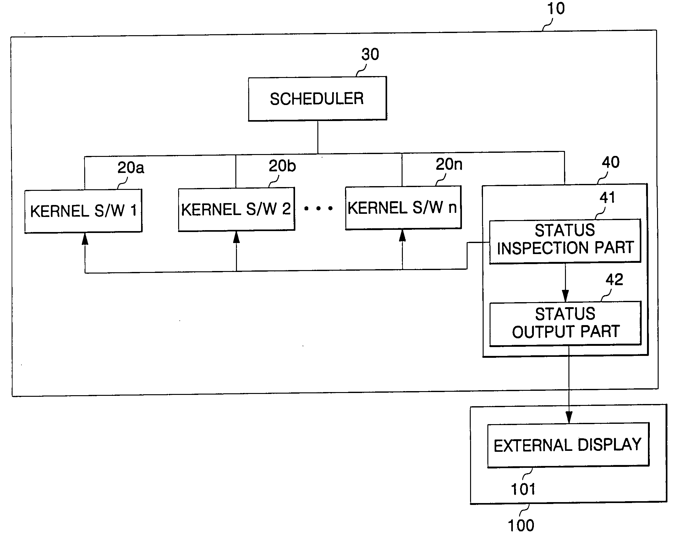
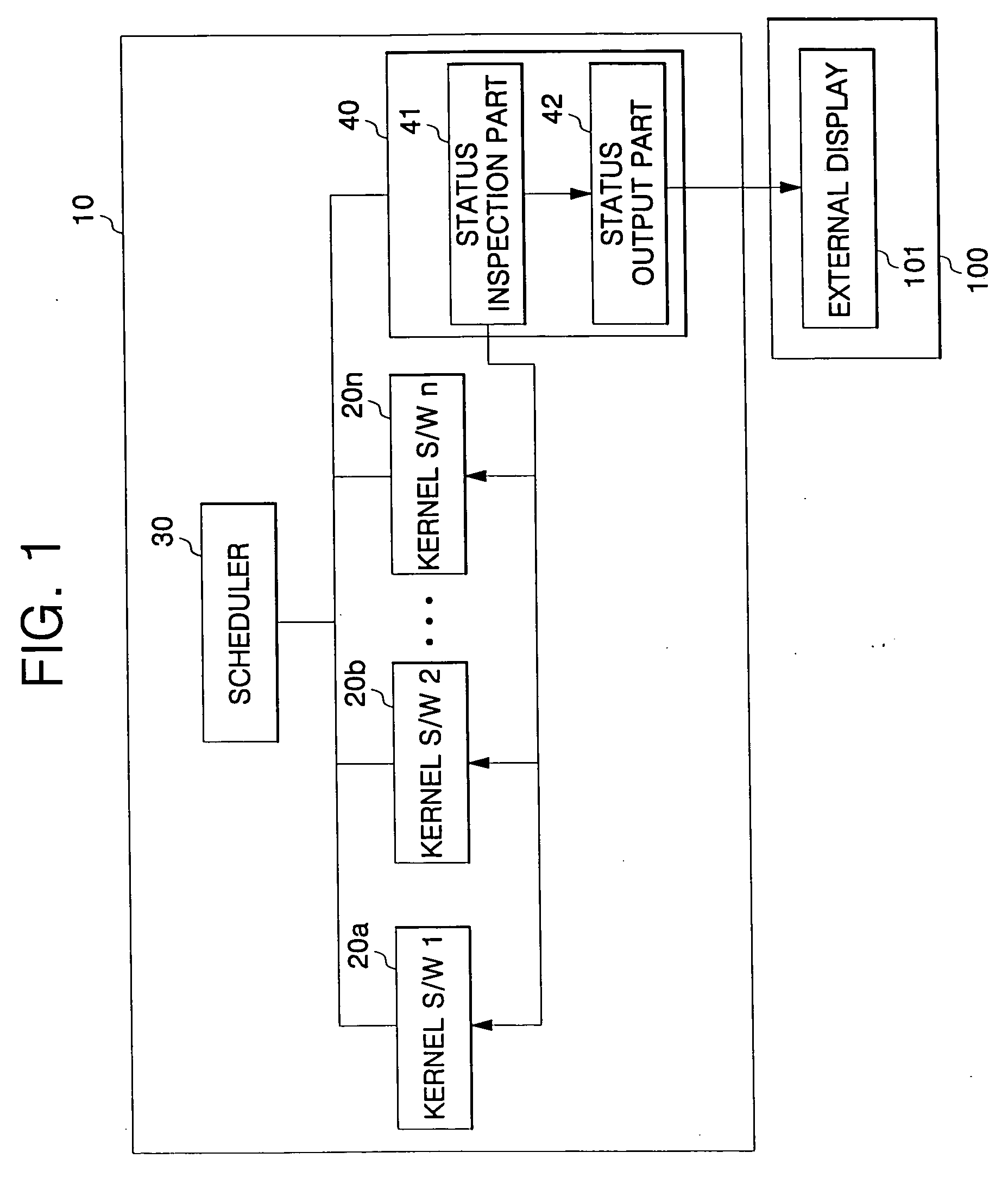
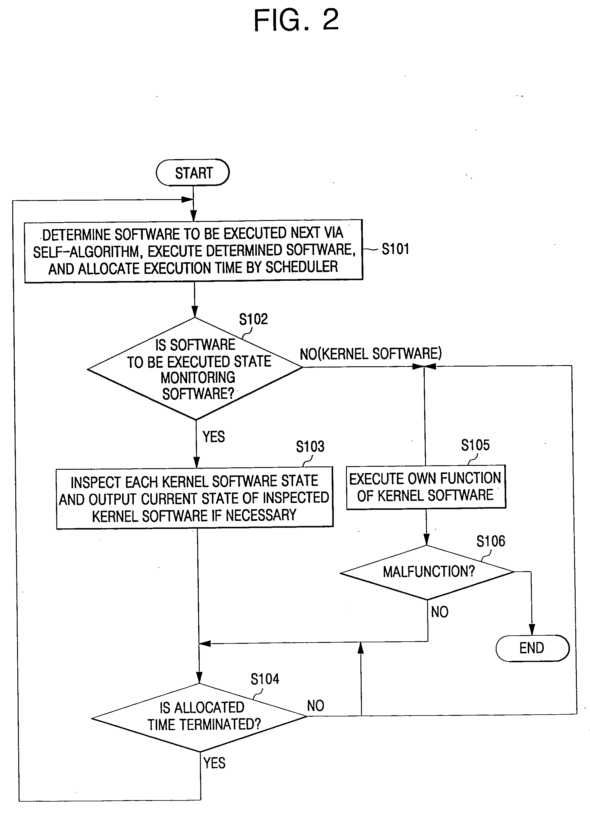
If any of the kernel software modules 20a to 20n malfunctions, a system panic occurs so that the system cannot be restored.
In this severe situation, the status monitoring software module 40 does not operate normally so that the user cannot confirm the internal state of the system.
Then, since the internal state of the system is not correctly inspected, approaches for solving the problems become difficult.
The primary reason of such a severe problem comes from an erroneously composed software.
Therefore, the foregoing severe situation can be rarely solved with software modules only, and thus needs the aid of a hardware logic.

Method used


Image

  • Apparatus and method for monitoring software module state in a system using an embedded multitasking OS
  • Apparatus and method for monitoring software module state in a system using an embedded multitasking OS
  • Apparatus and method for monitoring software module state in a system using an embedded multitasking OS

Examples


Embodiment Construction

[0077] Hereinafter an apparatus and method for monitoring software module state of a system using an embedded multitasking OS according to the invention will be described in detail with reference to the accompanying drawings.

[0078]FIG. 3 is a block diagram of an apparatus for monitoring software module state in a system using an embedded multitasking OS according to the present invention.

[0079] As shown in FIG. 3, the software module state monitoring apparatus in a system using an embedded multitasking OS according to the present invention is divided into an OS part 10 and a hardware logic 100, in which both parts operate totally independent from each other without any interaction to the operation state.

[0080] The OS part 10 includes a scheduler 30, a number of kernel software modules 20a to 20n and a state record setting part 50, and the hardware logic 100 includes a state recording part 140, a state reading part 130, a state output part 120, a display part 110 and an inspection...


PUM


Abstract

The apparatus and method for monitoring the software module state of the embedded multitasking operating system in a system using the embedded multitasking operating system according to the invention sequentially records the state information of the software modules in the state recording range of the hardware logic, sequentially reads the state information of the software modules from the state recording range, and displays the state information so that the user can easily recognize the same. As a result, the state information of the software modules can be monitored and inspected independent from the operation of the software modules of the operating system, and thus the state of the software modules or the operating system can be inspected in any exceptional software-associated situations.

Description

CLAIM OF PRIORITY [0001] This application makes reference to, incorporates the same herein, and claims all benefits accruing under 35 U.S.C. §119 from an application for APPARATUS AND METHOD FOR MONITORING SOFTWARE MODULE STATE IN SYSTEMS USING EMBEDDED MULTITASK OPERATING SYSTEM earlier filed in the Korean Intellectual Property Office on 27 Jan. 2004 and there duly assigned Serial No. 2004-5153. BACKGROUND OF THE INVENTION [0002] 1. Field of the Invention [0003] The present invention relates to an embedded multitasking operating system, and more particularly, to an apparatus and method for efficiently monitoring panics in a kernel or the internal state of a software module of an embedded multitasking operating system in a system using the embedded multitasking operating system. [0004] 2. Description of the Related Art [0005] In general, an operating system (hereinafter will be referred to as “OS”) used in an embedded system includes a kernel or a software module functioning as a co...

Claims


Application Information

Patent Timeline
IPC IPC(8): G06F11/00G06F9/46
CPCG06F11/0715G06F11/3055G06F11/302G06F11/3017A47K3/022A47K3/06
Inventor KIM, JIN-OHCHOE, BYUNG-GUPARK, YONG-SEOK
Owner SAMSUNG ELECTRONICS CO LTD
Learn More