Sound processing device, sound processing method, and sound processing program

Active Publication Date: 2015-03-05
HONDA MOTOR CO LTD
View PDF4 Cites 12 Cited by
  • Summary
  • Abstract
  • Description
  • Claims
  • Application Information

AI Technical Summary

Benefits of technology

[0020]According to the aspect of (2), it is possible to estimate an elevation angle of a sound source with a sound processing device having a decreased size.
[0021]According to the aspect of (3), it is possible to estimate an azimuth and an elevation angle so as to be more robust to disturbance, compared with a method of using sound signals and posture information at two times.
[0022]According to the aspect of (4) or (5), it is possible to display an azimuth estimated by the azimuth estimation unit and the elevation angle estimated by the elevation angle estimation unit as an image which can be easily intuitively recognized.
[0023]According to the aspect of

Problems solved by technology

However, in the above-mentioned technique, since a plurality of microphones are three-dimensionally arranged, t

Method used


Image

  • Sound processing device, sound processing method, and sound processing program
  • Sound processing device, sound processing method, and sound processing program
  • Sound processing device, sound processing method, and sound processing program

Examples


Example

First Embodiment

[0048]Hereinafter, a first embodiment of the present invention will be described with reference to the accompanying drawings.

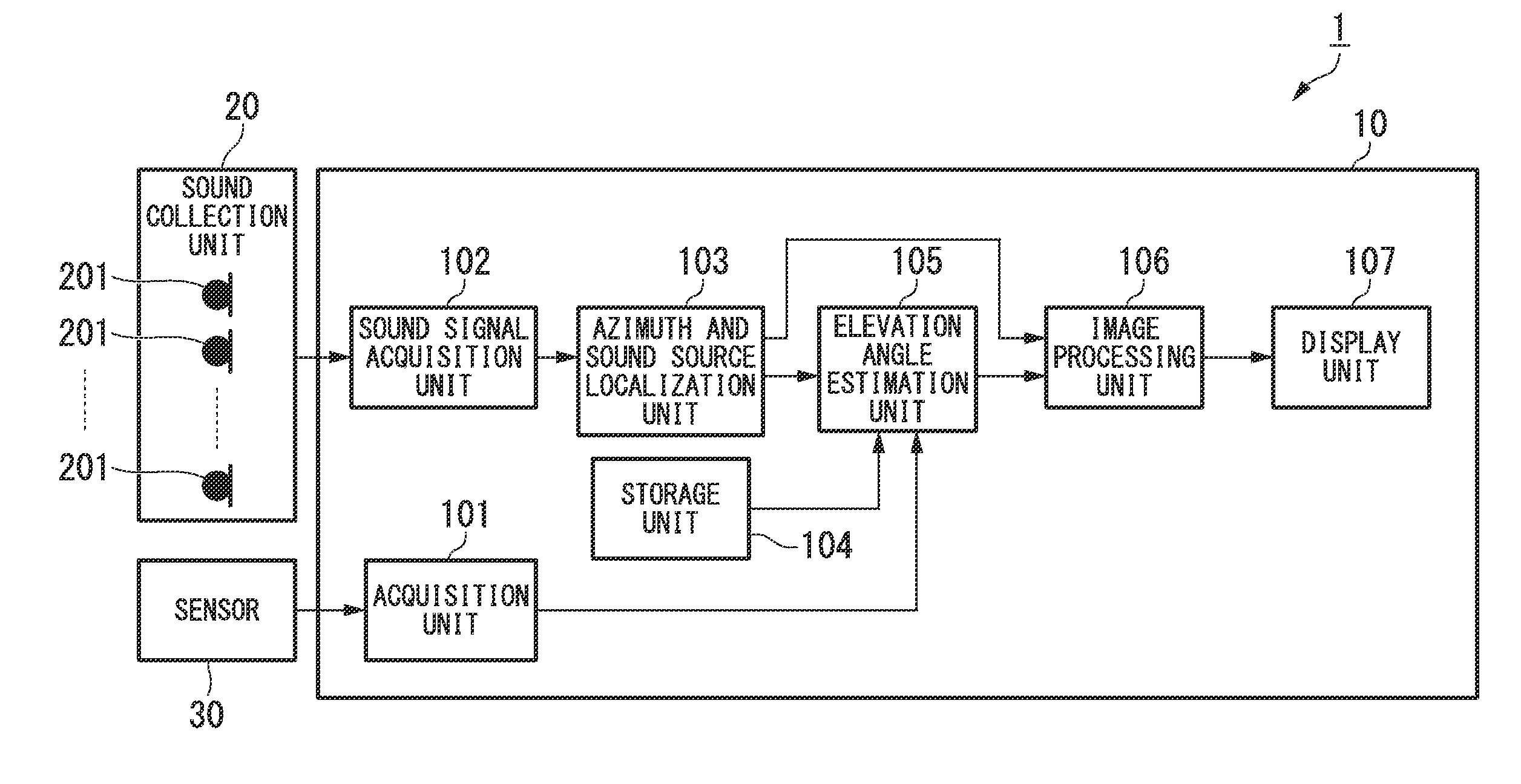
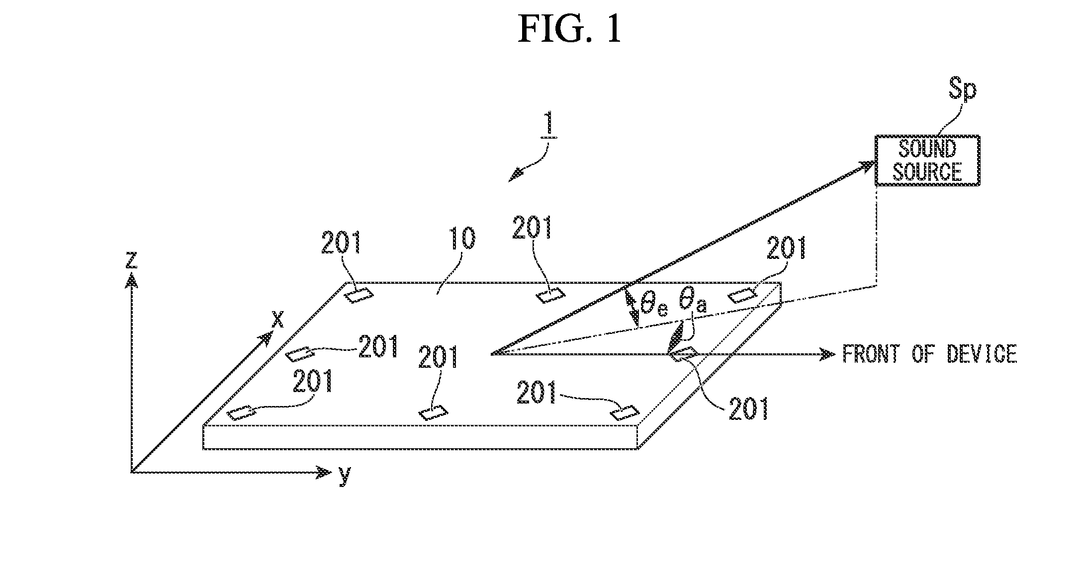
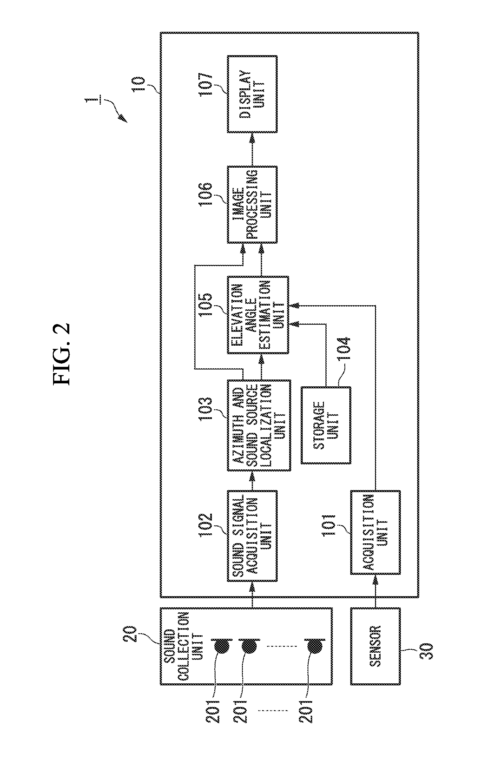
[0049]FIG. 1 is a diagram showing an arrangement example of a sound processing system 1 according to the first embodiment. As shown in FIG. 1, the sound processing system 1 includes a sound processing device 10 and eight microphones 201. As shown in FIG. 1, the eight microphones 201 are attached substantially in the surrounding part of the sound processing device 10. The number of and arrangement of the microphones 201 shown in FIG. 1 are an example and the number and arrangement of the microphones 201 are not limited to this example.

[0050]In this arrangement example, the short-length direction of the sound processing device 10 is defined as an x axis direction, the longitudinal direction is defined as a y axis direction, and the thickness direction is defined as the z axis direction. As shown in FIG. 1, the right side on the drawing surface in...

Example

Second Embodiment

[0107]The first embodiment has described the example where the azimuth and the elevation angle of a sound source are estimated based on the sound signals acquired at two frames and the rotation angle information as the posture information of the device.

[0108]In a second embodiment, a sound source position is estimated by smoothing and optimizing sound source positions estimated at a plurality of frames using a Bound Optimization BY Quadratic Approximation (BOBYQA) method (for example, see Non-patent Document 1).[0109]Non-patent Document 1: M. J. D. Powell, “The BOBYQA algorithm for bound constrained optimization without derivatives”, Report DAMTP 2009 / NA06, 2009

[0110]FIG. 8 is a block diagram showing a configuration of a sound processing device 10A according to the second embodiment. As shown in FIG. 8, the sound processing device 10A includes an acquisition unit (tilt information acquisition unit) 101, a sound signal acquisition unit 102, an azimuth and sound sourc...

Example

Third Embodiment

[0134]The first embodiment and the second embodiment have described the example where the estimated azimuth and the estimated elevation angle are displayed on the display unit 107, and a third embodiment of the present invention describes an example where the direction of a sound source Sp is displayed on the display unit 107 based on the estimated azimuth and the elevation angle.

[0135]FIG. 11 is a block diagram showing a configuration of a sound processing device 10B according to the third embodiment. As shown in FIG. 11, the sound processing device 10B includes an acquisition unit (tilt information acquisition unit) 101, a sound signal acquisition unit 102, an azimuth and sound source localization unit (azimuth estimation unit) 103, a storage unit 104, an elevation angle estimation unit 105, an image processing unit 106B, a display unit 107, and an image acquisition unit 121. The sound processing device 10B is connected to a sound collection unit 20, a sensor 30, a...


PUM


Abstract

A sound processing device includes a sound collection unit configured to record a sound signal, a tilt information acquisition unit configured to acquire tilt information on a tilt of the sound processing device, an azimuth estimation unit configured to estimate azimuths of a sound source in a plane in which the sound collection unit is arranged based on the sound signals which are recorded by the sound collection unit at least at two times; and an elevation angle estimation unit configured to estimate an elevation angle of the sound source with respect to the plane in which the sound collection unit is arranged based on the tilt information acquired by the tilt information acquisition unit and the azimuths estimated by the azimuth estimation unit at least at two times.

Description

CROSS REFERENCE TO RELATED APPLICATIONS[0001]Priority is claimed on Japanese Patent Application No. 2013-180672, filed on Aug. 30, 2013, the contents of which are entirely incorporated herein by reference.BACKGROUND OF THE INVENTION[0002]1. Field of the Invention[0003]The present invention relates to a sound processing device, a sound processing method, and a sound processing program.[0004]2. Description of Related Art[0005]A system has been proposed which estimates a direction or a position of a sound source and notifies a user of the estimated sound source information (for example, see Japanese Unexamined Patent Application, First Publication No. 2008-197650 (Patent Document 1). In the technique described in Patent Document 1, sound data is recorded with eight microphones and sound source localization is performed on the recorded sound data based on a cross-correlation between a pair of microphones. In the technique described in Patent Document 1, seven normal microphones and one ...

Claims


Application Information

Patent Timeline
IPC IPC(8): G01S3/802G06T11/20
CPCG06T11/206G01S3/802
Inventor NAKADAI, KAZUHIRONAKAMURA, KEISUKESINAPAYEN, LANAIMAI, MICHITA
Owner HONDA MOTOR CO LTD
Why Eureka
Try Eureka