Optical Recording/Reproducing Apparatus, Optical Recording Method, and Optical Reproduction Method
Inactive Publication Date: 2008-12-25
FUJIFILM CORP
View PDF6 Cites 14 Cited by
Summary
Abstract
Description
Claims
Application Information
AI Technical Summary
This helps you quickly interpret patents by identifying the three key elements:
Problems solved by technology
Method used
Benefits of technology
Benefits of technology
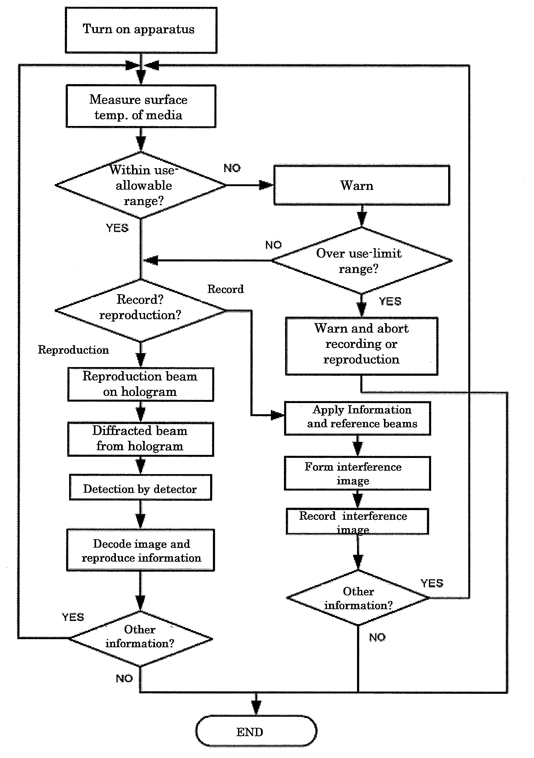
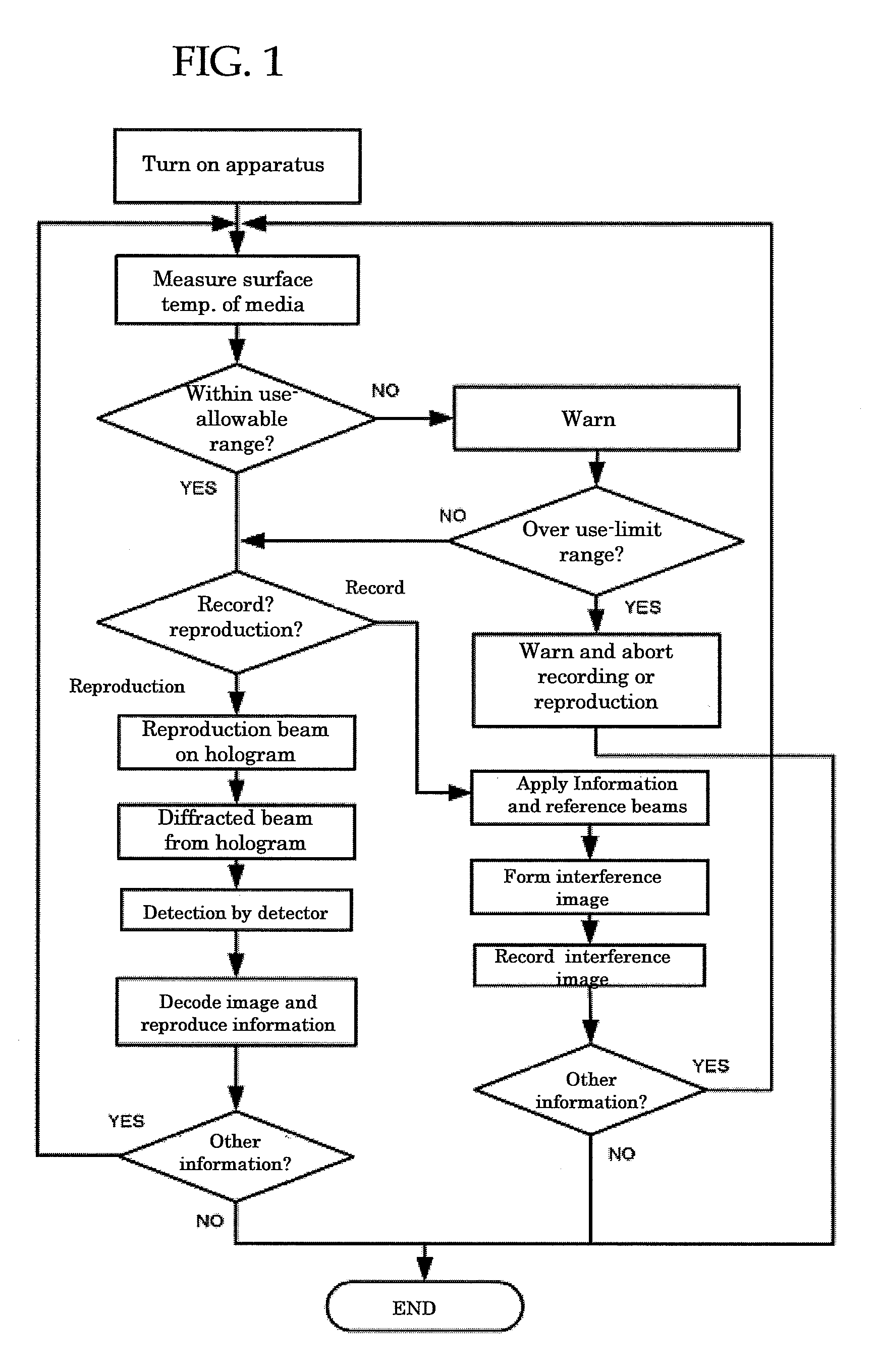
[0021]It is an object of the present invention to solve the foregoing problem pertinent in the art and to achieve the following object. More specifically, it is an object of the present invention to provide an optical recording / reproducing apparatus, optical recording method and optical reproduction method, which can easily recognize whether or not the surface temperature of an optical recording medium capable of multiplexing recording by collinear holography is outside the allowable use temperature range and thus can achieve excellent reproduction free from displacement or deformation of image.
[0040]In the optical recording / reproducing apparatus according to <17>, there are two or more cholesteric liquid crystallayers and thus there is no changes in the selective reflectionwavelength due to changes in the incident angle, and neither of the information beam, reference beam and reproduction used for recording or reproduction reaches the reflective film. Thus, generation of light diffusion due to diffused reflection on the reflection surface can be avoided. Accordingly, noises that occur due to the diffused light are not superimposed with the reproduced image and thus are not detected by a CMOS sensor or CCD, allowing detection of the reproduced image to an extent that enables error correction. The noise component due to diffused light becomes more problematic as the degree of multiplexing of holograms increases. More specifically, as the degree of multiplexing increases, e.g., to 10 or higher, the diffraction efficiency per hologram significantly decreases. Thus the presence of the noise component due to diffused light makes detection of the reproduced image very difficult. With this configuration, such difficulty can be overcome and unprecedented high-density image recording can be achieved.
[0070]According to the present invention, it is possible to solve the problems pertinent in the art and to provide an optical recording / reproducing apparatus, optical recording method and optical reproduction method, which can easily recognize whether or not the surface temperature of an optical recording medium capable of multiplexing recording by collinear holography is outside the allowable use temperature range and thus can achieve excellent reproduction free from displacement or deformation of image.
Problems solved by technology
In this reproduction method, however, when the incident angle of the reproduction beam 38a has deviated from that of the reference beam for recording or when the focal distance of the reproduction beam 38a in the optical direction has deviated from that of the reference beam as shown in FIGS. 5 and 6, the direction in which the diffracted beam 39 travels tilts from the original vertical direction by, for example, angle θ, leading to generation of a reproduced interference image that is not identical to the true interference image to be detected by the detector and resulting in failure to perform proper reproduction.
A possible cause of such displacement and deformation is that the optical recording medium undergoes surface temperature changes during recording and reproduction, so that the incident angles and focal distances in the optical direction of the information beam, reference beam and reproduction beam deviate.
For example, when an optical recording medium that has been written at a media surface temperature of 40° C.—a temperature exceeding the pre-set use temperature range of 20° C. to 30° C.—is reproduced at a surface temperature of 50° C., reproduction may fail due to significant influences of the above-noted deviation or deformation.
Moreover, reproduction may fail when attempting to reproduce information from an optical recording medium at a surface temperature of 40° C., which optical recording medium has been written at a surface temperature of 25° C., a temperature that falls within the use temperature range.
On the other hand, even when the optical recording medium has been written with the surface temperature falling within the use temperature range, falling outside that use temperature range upon recording similarly leads to displacement or deformation of interference image.
Method used
Image
Click on the blue label to locate the original text in one second.
Reading with bidirectional positioning of images and text.
[0395]FIGS. 18 and 20 are schematic cross-sectional views showing the structure of an optical recording medium of the specific example 1 of the present invention. In the optical recording medium 21 according to this specific example 1 servo pit patterns 3 are formed on a second substrate 1 made of polycarbonate resin or glass, and the serve pit patterns 3 are coated with Al, Au, Pt or the like to form a reflective film 2. Although the servo pit patterns 3 are shown to be formed on the entire surface of the second substrate 1 in FIG. 20, it may be formed on the second substrate 1 periodically. In addition, the height of the servo pit patterns 3 are generally 1,750 angstrom (175 nm), far smaller than those of the other layers, including substrates.
[0396]A first gap layer 8 is formed by applying a material such as a UV curable resin over the reflective film 2 of the second substrate 1 by spin coating or the like. The first gap layer 8 protects the reflective ...
[0403]FIG. 21 is a schematic cross sectional view of the structure of an optical recording medium in specific example 2. The optical recording medium 22 is identical to that of specific example 1 except for the structure of the filter layer 6.
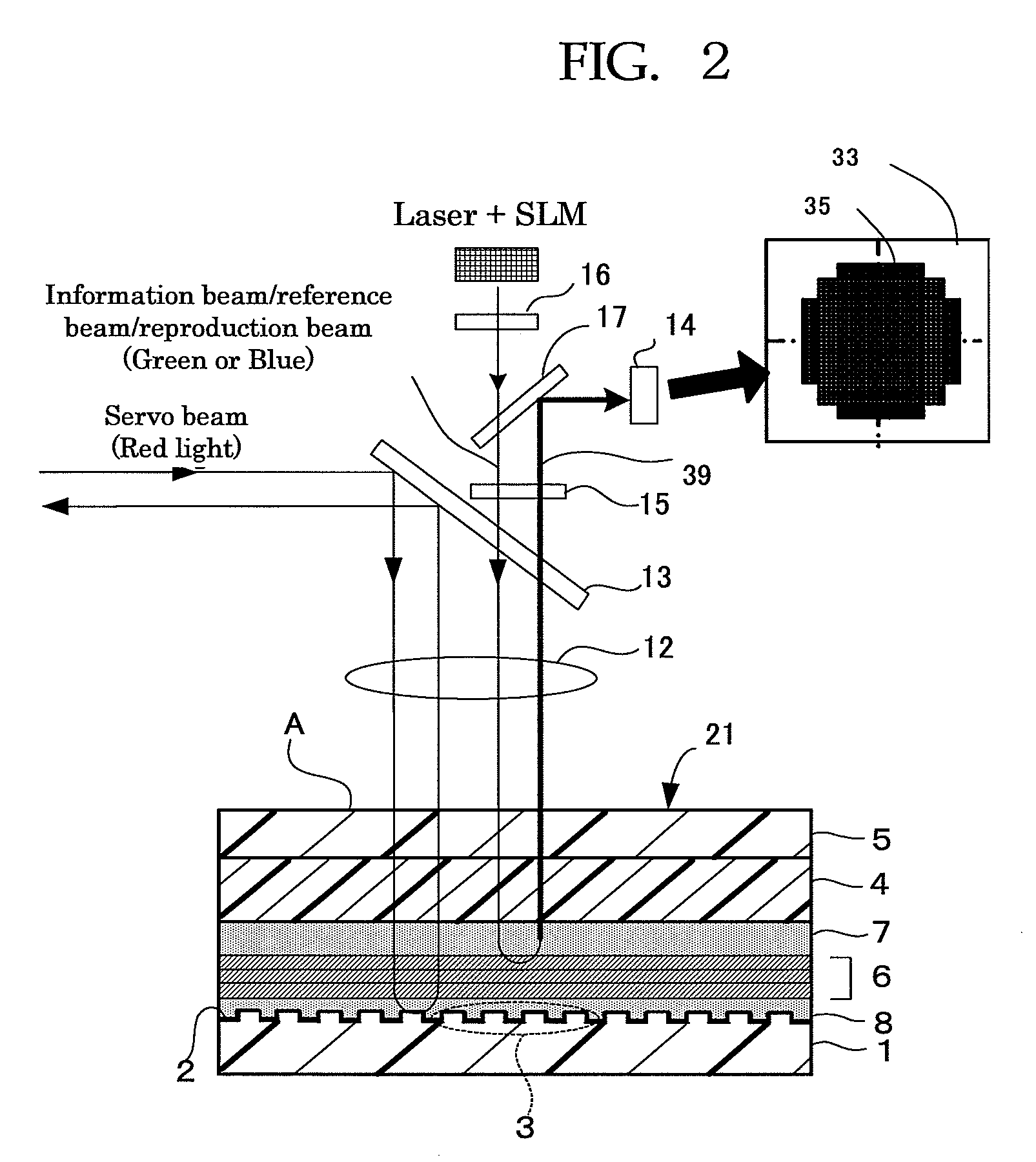
[0404]In FIG. 21, the filter layer 6 transmits therein only a red light beam and reflects light beams of the other colors. Thus, the information and reference beams for recording and reproduction do not pass through the filter layer 6 because they are green or blue light, and never reach the reflective film 2, becoming returning beams emitting from light entrance / exit surface A.
[0405]This filter layer 6 is a laminate formed of a dielectric material-deposited layer consisting of 7 thin dielectric films with different refractive indices provided on a coloring material-containing layer. The filter layer 6 composed of the coloring material-containing layer and dielectric material-deposited layer may be directly formed on ...
[0410]An optical recording medium of Example 1 was prepared by depositing on a first substrate, in sequence, a recording layer, a second gap layer, a filter layer, a first gap layer, and a second substrate in a manner described below. The filter layer was prepared by depositing a film-shaped filter prepared as follows.
Preparation of Filter Layer
—Formation of Coloring Material-Containing Layer—
[0411]At first, polyvinyl alcohol (MP 203, from Kuraray Co., Ltd.) was applied on a polycarbonate film of 100 μm thickness (Iupilon, from Mitsubishi Gas Chemical Company Inc.) to a thickness of 1 μm to prepare a base film.
[0412]Next, coating solution for coloring material-containing layer containing the following components was prepared with a normal method.
PUM
Abstract
To provide an optical recording / reproducing apparatus, optical recording method and optical reproduction method, which can easily recognize whether or not the surface temperature of an optical recording medium capable of multiplexing recording by collinear holography is outside the allowable use temperature range and thus can achieve excellent reproduction free from displacement or deformation of image. The apparatus performs at least one of recording by application of an information beam and a reference beam to an optical recording medium having a recording layer for recording information by holography, and reproduction of information by application of a reproduction beam, and comprises at least one of: a warning unit configured to inform that, upon recording or reproduction, a surface temperature of the optical recording medium has fallen outside a use-allowable temperature range with respect to a reference temperature; and an aborting unit configured to display the fact that at least one of recording and reproduction will be aborted and abort the recording and reproduction, when the surface temperature has fallen outside a use-limit temperature range with respect to the reference temperature. Moreover, it is preferably an optical recording method or optical reproduction method.
Description
TECHNICAL FIELD[0001]The present invention relates to an optical recording / reproducing apparatus, optical recording method and optical reproduction method for recording on or reproducing from an optical recording medium having a recording layer for recording information by holography. More particularly, the present invention relates to an optical recording / reproducing apparatus, optical recording method and optical reproduction method, which are capable of normal recording or reproduction within an allowable temperature range of the optical recording medium and of obtaining high signal-to-noise ratios (SNR) upon recording and reproduction.BACKGROUND ART[0002]A method for recording on an optical recording medium by holography generally utilizes optical interference between an image information-carrying information beam (object beam) and a reference beam inside the medium to produce an interference image (interference fringes), and records it in the medium.[0003]Holographic optical re...
Claims
Application Information
Patent Timeline
Application Date:The date an application was filed.
Publication Date:The date a patent or application was officially published.
First Publication Date:The earliest publication date of a patent with the same application number.
Issue Date:Publication date of the patent grant document.
PCT Entry Date:The Entry date of PCT National Phase.
Estimated Expiry Date:The statutory expiry date of a patent right according to the Patent Law, and it is the longest term of protection that the patent right can achieve without the termination of the patent right due to other reasons(Term extension factor has been taken into account ).
Invalid Date:Actual expiry date is based on effective date or publication date of legal transaction data of invalid patent.

