Led-based light engine

a technology of led light engine and led battery, which is applied in the direction of semiconductor devices for light sources, fixed installations, lighting and heating apparatus, etc., can solve the problems of not having long operating lifetime, requiring frequent replacement, and gas-filled tubes such as fluorescent or neon tubes, which may have longer lifetimes, etc., to preserve led lifetime and efficient heat evacuation

Inactive Publication Date: 2010-09-09
DIAMOND CREEK CAPITAL LLC
View PDF100 Cites 95 Cited by
  • Summary
  • Abstract
  • Description
  • Claims
  • Application Information

AI Technical Summary

Benefits of technology

[0008]Accordingly, there is a need in the art for lighting systems utilizing LEDs and which efficiently evacuate heat away from the LEDs so as to preserve LED lifetime.

Problems solved by technology

Incandescent bulbs typically do not have long operating lifetimes and thus require frequent replacement.
Gas-filled tubes, such as fluorescent or neon tubes, may have longer lifetimes, but operate using dangerously high voltages, are relatively expensive, and include hazardous materials such as mercury.
Further, both bulbs and gas-filled tubes consume substantial amounts of power.
Excessive heat reduces the efficiency and lifetime of the LED.
However, such increased brightness is accompanied by increased heat-generation.

Method used


Image

  • Led-based light engine
  • Led-based light engine
  • Led-based light engine

Examples


Embodiment Construction

[0054]The present specification and figures present and discuss embodiments of light emitting diode (LED) modules and LED-based luminaires and LED-based light engines that employ such modules. Structure for the illustrated embodiments is discussed herein, as are methods for making such embodiments in accordance with the structure. It is to be understood that the specific embodiments disclosed herein are presented as examples, and the technology and principles described herein can be applied to other configurations and technologies that involve a circuit board with componentry mounted thereon.

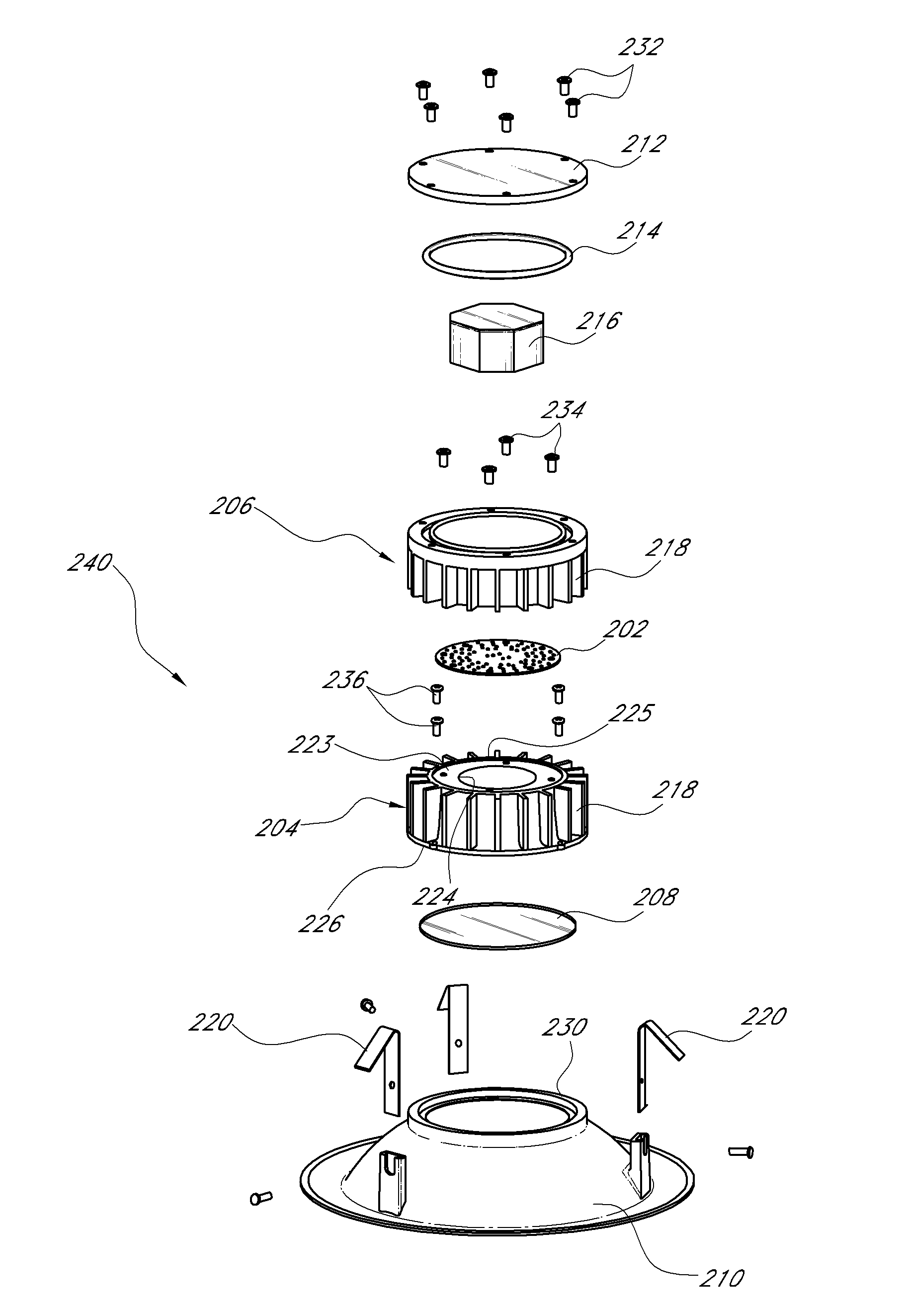
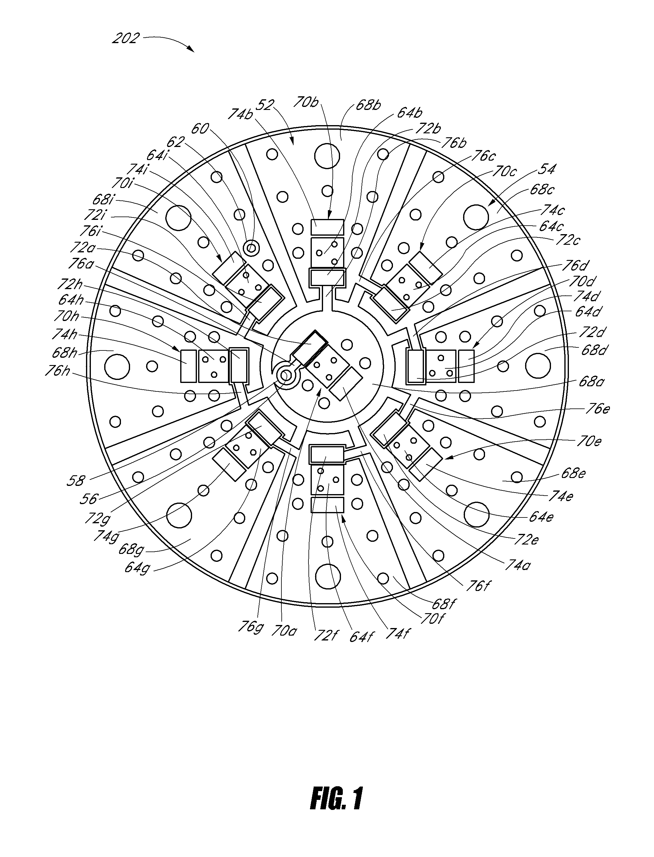
[0055]FIGS. 1 and 2 illustrate one embodiment of a light emitting diode (LED) lighting module, which is adapted to provide light for an LED-based luminaire. The LED module 202 comprises a printed circuit board 52 upon which LEDs and associated power delivery circuitry is mounted. FIG. 1 shows a first, or front, face 54 of the circuit board 52 and FIG. 2 shows a second, or back, face 842 of the p...


PUM


Abstract

An LED-based luminaire employs an LED module mounted to a housing. The LED module is advantageously configured to transmit heat generated by the LEDs across and / or through the module and to the housing for dispersal to the environment. LED modules can be configured with conductive or non-conductive cores, and may be configured to evacuate heat from one or both faces of the LED module. Further, multiple heat paths can be defined from components on an LED module to the housing and to the environment.

Description

CROSS-REFERENCE TO RELATED APPLICATIONS[0001]This application claims the benefit of U.S. Provisional Application Nos. 61 / 171,741, filed on Apr. 22, 2009, 61 / 154,106, filed on Feb. 20, 2009, 61 / 152,202, filed on Feb. 12, 2009, and 61 / 120,390, filed on Dec. 5, 2008. The entireties of each of these priority applications are hereby incorporated by reference.BACKGROUND OF THE INVENTION[0002]1. Field of the Invention[0003]The present invention is in the field of illumination devices and, more specifically, light emitting diode (LED)-based illumination devices.[0004]2. Description of the Related Art[0005]Most lighting applications utilize incandescent or gas-filled bulbs, particularly lighting applications that require more than a low level of illumination. Incandescent bulbs typically do not have long operating lifetimes and thus require frequent replacement. Gas-filled tubes, such as fluorescent or neon tubes, may have longer lifetimes, but operate using dangerously high voltages, are re...

Claims


Application Information

Patent Timeline
Patent Type & Authority Applications(United States)
IPC IPC(8): H01L33/64
CPCF21S8/02F21V29/004F21V29/773Y10S362/80F21Y2101/02F21Y2115/10F21V29/507F21V29/71
Inventor LYNCH, FERNANDOSTEEDLY, JAMESBREMSER, MICHAELKOHAN, KAMRANKEAN, JOHNNY
Owner DIAMOND CREEK CAPITAL LLC
Why Eureka
Try Eureka